Hi Mike,
Excellent! That was pretty fast too.
So, did it answer your questions?
-Chris
Excellent! That was pretty fast too.
So, did it answer your questions?
Now that sounds like a worthwhile project Mike! I'd go for it, and it sounds like you are.Im thinking about re-jigging this for the CDP input so while using the CDP the signal isnt passing the selector ic. The realy would be activated by the 'direct' switch. Do you get the idea? It seems easily do-able and the relay is close to the rear panel so the signal path wont be extended considerably. I need that manual though so I can see whats going on.
-Chris
Hi Chris.
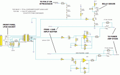
The circuit is as I suspected.
When a plug is inserted into the i-Pod socket the relay activates, switching out the selector ic and +12 gain buffer and switching in the +24 gain buffer.
Therfore, it can be used for the CDP input thus removing the selector ic from the signal path while listening to CD! (I might invest in a new relay with gold or silver contacts). I dont know if it will require a latching push button switch or not. Ideally Id like to rig it so the existing (non-latching) CDP button (and LED) still works. Is it just a pulse that open and closes the relay?
Later I will post some pics of the circuit.
Mike.
Hi Mike,
-Chris
A normal sealed, gas filled telecommunications relay would be what you want here, coil voltages are commonly 6, 12 and 24 VDC. You may find 5 and 9 volt coils also.(I might invest in a new relay with gold or silver contacts).
Yes, not unless you want to build a circuit. Most relays require the normally open contacts to have the coil constantly energized. You can get pulse type relays, but those are more expensive.I dont know if it will require a latching push button switch or not.
The same question as above. On normal relays, the coil needs to be constantly energized to close the normally open contacts.Is it just a pulse that open and closes the relay?
-Chris
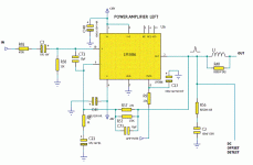
C72 is the input RF filter. It's a bit small, could it be 330pF?
C73 is a compensation for the HF response of the chipamp.
C3 is too big relative to C22. If a smaller DC blocking cap is fitted to the source then the two caps operate in series to give a lower effective value.
Increase C22 to 150uF if you can squeeze it in.
If there is no DC blocking in the source then reduce C3 to 4.4uF or 4.7uF.
If there is DC blocking in both source and poweramp then you can add a bypass to the power amp (labelled DC input), tapping into the top of R58. But add a series resistor, ~1k0 to make the RF filter work.
Its tempting to whip out all the 'extra' components and go for a minimalist set up employed by many chipamp builders. However, with this being an integrated there is likely much more filtering needed to reduce noise etc.
Those 2 ceramics are in the signal path so they are potential victims for replacement with silver mica or polystyrene. If the value is low (as Andrew suggests) it can be replaced for a higher value. The BOM in the manual also reads 33pF. Theres always the cance the amp could sound better without them....
Another feature not shown in the 340A sevice manual is that there are also small ceramics at the speaker outputs (labeled EMC supression). 1nF from SPKR ground to mains ground. Any idea what these are for and if changing to mica or pplyprop (for example) might sound better?
C3 is too big relative to C22. If a smaller DC blocking cap is fitted to the source then the two caps operate in series to give a lower effective value.
Hi Andrew.
Im confused about this feedback cap. On another forum I was advised that using a 22uF wima MKS2-XL would be great in the feedback and that I wouldnt get any audible decrease in bass as the low cut off would be below what most speakers can produce anyway. But you advise to increase it considerably? I dont get it. I know you mentioned earlier that the low bass allthough not audible can give a more natural sound? How is this the case if it cant be heard anyway? Im not being argumentive, Im just a little confused by the conflicting data.
The National Semi datasheet suggests a 22uF in this position with 1K0 resistor.
National Semi LM3886 suggested set up.
A mate on PFM gave me a pair of 47uF wima polyprops. Theyre big obviously but theres an easy soloution to fit them. Over on fish the 'in thing' is the wima 22uf mks2-xl's in feedback. Apparently these give amazing results in Naim equipment.
Anyone know where to get a suitable 300VA trafo in the UK?
Also, am I right that the supply voltage to the chip determines its power output? The amp is rated at 45w/pc @ 8 ohms (55 @ 4ohm). So there is the potential to get about 10 extra watts just by upping hte supply voltage?
Another consideration: Is it ok to use an over rated trafo if you attenuate the output to the required voltage. Is there any benefit to this such as improved regultaion or increased headroom?
As I mentioned some pages ago - http://www.airlinktransformers.com/. Similar price to Farnell but perhaps nicer quality and no minimum order or account required.
500VA is cheaper than 300VA (probably due to demand) so get one of those if you can fit it in somehow.
If you up the supply voltage it will go louder into 8ohms but will be a problem for 4ohms. There's a graph that illustrates this somewhere - have a good look on the LM3886 datasheet, it's probably there. I think 20VAC secondaries are about right for 4 ohm speakers.
Simon
SimontY said:Have you installed them yet Mike? 😀
No.
Nothing goes in until I cure the buzz problem I have (there a link to the troubleshooting thread in an earlier post). Also I dont want to do anything until Im 100% certain of the changes I make. So far there are several things Im defo gonna do, but a few more things to work out and more parts to source first. Trust me, this'll be a good one!
Im looking into using the front panel LED's to feed the relay driver circuits. This way I can use the micro to control a relay input switching array. 🙂
Mike.
I think 20VAC secondaries are about right for 4 ohm speakers.
No idea what rating my RTL2's are.......
I had them running on a 840A and the bass sounded ace, they like power!!!!
The bass will improve from using a bigger transformer. The whole sound should become more effortless.
The stock trafo has 24v secondaries, 28v after rectifier.
I checked the 500VA ones, wont fit. The 300va ones are availble with 25v secondaries and will just about fit, whats that after rectification? Also they existing trafo is centre tapped and these airlink ones arent? Do I just twist each 0v lead together to use it?
I checked the 500VA ones, wont fit. The 300va ones are availble with 25v secondaries and will just about fit, whats that after rectification? Also they existing trafo is centre tapped and these airlink ones arent? Do I just twist each 0v lead together to use it?
25v secondaries = 35vdc unloaded (from memory of my own amp).
To get the 0v / centre tap you connect one half of each secondary together. This turns your 25 - 0, 25 - 0 into +35 - 0 - -35 essentially (after rectification).
You need to connect the black and orange wires I think (if using an Airlink tx)!!!
Would appreciate a technical guy to confirm this.
Also, a transformer with 22V windings will probably give you more usable power.... but I can't find much info on your TDLs from Google
Thanks,
Simon
- Status
- Not open for further replies.
- Home
- Amplifiers
- Chip Amps
- CA 340A SE LM3886 based amp - Upgrade advice please.