Honestly, if you were fitting these to the Cambridge board, it isnt going to make much difference. The power traces on the PCB aren't very thick, and would be useless at carrying that sort of current.
If you're sticking with the Cambridge PCB, what I would simply do is get some good quality 220nF capacitors, and solder them between the pins of the existing power supply capacitors.
If you're sticking with the Cambridge PCB, what I would simply do is get some good quality 220nF capacitors, and solder them between the pins of the existing power supply capacitors.
Hi Mike,
I've just stumbled across this thread and I'm disappointed to see that 4 pages of content could easily have been put into about 2 posts.
Anyway, now that I've deleted what I decided wasn't a clever thing to say, I'll try to help you achieve what you want.
Basically, you have a chip amp built around a good sounding chip that can put out very good power and current. There's no scope for ultimate high end sound because so much of what matters is already built into the chip and decided for you!
So you're left with adjusting the pre-amp section, gain, general components and the power supply. And, if you like, the chassis/resonance.
I have built an LM3886 amp myself, and found the sound to be very good. The power supply capacitors have a big influence on the sound, so this is something you need to get right.
I have 2 x 100VA transformers (dual mono). Then ordinary bridges. Then 2 x 3300uF per side. This was fine.
I then made it 4 x 3300uF per side (BC Components 40V caps) and the bass improved substantially. I then added the famous controversial "CarlosFM snubber" to the caps and found enhanced freshness to the sound. This was something like 1R in series with 220nF (polyester) placed across the power capacitor terminals. Technically, this may work by improving the effectiveness of the capacitor across a range of very high frequencies. But in practical terms it's cheap to try and nobody's said it will hurt anything. The degree of improvement may depend on the performance of the main smoothing caps.
You must consider localised power supply decoupling (right on the chips' pins) - I used 100uF Rubycon ZL with good results but I expect the ZA range would be even better, and there are always Black Gates and other fun stuff. It's probably a waste of time putting small film caps here as the ESR may be too high to have any effect.
Another thing to look at is the transformer. Bigger is usually better - 300VA would be about right for 2 channels. Rail voltage is a factor too - it has been suggested that a lower voltage will sound smoother and a higher voltage more exciting with tighter bass. It's worth noting that a lower voltage will enable 4ohm speakers to pull the chip's full power of 68W RMS, whereas a too high voltage (over >30V+-) will not work so well.
Just some thoughts about what makes the most difference. More to add.
Simon
I know you've considered the rectifier diodes but it's probably not worth investing too much here, as whilst they may change the sound it won't necessarily be more pleasant. I once changed to large schottky diodes on an amp and it did sound very different, but it was very bright sounding and I'm not sure it was better! I sold the amp so I didn't investigate any further.
Simon
Simon
Your suggestion of all those bypassing caps could be interesting - I think CarlosFM (I wonder why the guy's now banned btw) did such a thing for an amp. Bear in mind that people who listen to these things have often found one cap or multiples of the same can sound better than various caps. Something big and nice like a 15000uF Mundorf M-Lytic with snubber might get a decent result for not much money or work.
I've just had another look at the schematic on page one and I would look at doing the following:
* replace C3 with a wire link (or bypass the whole trace with good wire)
* replace L1 & R48 with a wire link (it doesn't do anything you need)
* bypass C22, again it's not needed
* change C40 & C41 for Rubycon ZA ~100uF and, if possible, mount on chips' pins
* change R57, R53 & R82 for Kiwame 2W resistors or whichever type you favour
I like Kiwame because they're cheap, green and have a benign sonic signature (if any). They're actually industrial types that someone discovered sound good!
Another idea would be to use the chassis and chips and heatsinks but to throw away the PCB and start again 🙂
I see you used the LM4562, which is a great choice of op-amps. I've listened to these (blindly) versus discrete buffers and they are very close in character!
Simon
Another look at the pics and I see a few things that strike me as less than ideal:
* loads of fuses
* varistors/MOVs at the power input
* why is the PCB so bleedin' huge?!
* volume pot might not be great
* transformer too small for 2 channels
* tx shared between power & preamp
I notice there's been talk of the transformer size. It looks like it's about 120-200VA to me. Will the case accommodate a taller one?
Could you slip in a new, small tx for the preamp? Something like a 30VA toroid will work nicely for the money.
Simon
Hi Simon.
I found a UK company (Pilton) who have a 300VA trafo - 60h x 110dia. Should just fit.
Considring taking a hacksaw the PCB Just leave the preamp and slector chip there. Add big Tx + Gainclone kit. Good pot etc.....wire it all up with Mundorf Silver/gold wire 😉 Cool.
I found a UK company (Pilton) who have a 300VA trafo - 60h x 110dia. Should just fit.
Considring taking a hacksaw the PCB
Just leave the preamp and slector chip there. Add big Tx + Gainclone kit. Good pot etc.....wire it all up with Mundorf Silver/gold wire 😉 Cool.Also, FYI, a Gainclone refers to an amp design closely resembling the 47 Labs Gaincard, a notorious amp! Notorious because it is evidently cheap to make but expensive to buy.
It uses the LM3875 chip (like LM3886 but lower powered and with no muting pin, and not good for 4ohm loads), 1000uF smoothing per rail (Black Gates) and has a 160VA R-core transformer, which is mounted in an external box called "power humpty" or something lol
To call an amp like the CA a "gainclone" is incorrect.
If you look up Peter Daniel and his various projects you'll see he's done a gainclone and then gone on to rigorously test every part, including heat sink materials and many diode types to find his perfect sound. In my humble opinion that's time he could have used building a class A amp but I've no doubt he has gained some valuable insights into component effects on sound quality, and he's famed for making stunning metalwork, so it's all pretty cool!
Simon
mikesnowdon said:Hi Simon.
I found a UK company (Pilton) who have a 300VA trafo - 60h x 110dia. Should just fit.
Considring taking a hacksaw the PCB
Mike,
300VA sounds nice 🙂
Selector chip sounds, erm, interesting. You don't really need a kit for a LM3886 as there's so little soldering work and so few parts. But a kit/PCB does mean less chance of explosions, which is nice.
Good pot - Alps Blue motorised is a good sounding and technically good (channel balance/tracking) choice. Not many others are motorised.
Mundorf silver/gold wire is interesting. I'm evaluating an interconnect made using this and whilst it's pleasant, it's somewhat coloured to these ears. It's on the sweet side of neutral, but without the fullest clarity of an expensive silver only interconnect. You'll not hate it though, that's for sure, and it's good value.
Simon
Simon
I could squeeze it all in with the existing PCB but sombody voiced a consideration on the Cambridge PCB's ability to carry current to the chips? I said I could wire the new PSU direct to the chip with appropriate wire but noboby has told me if this is a good idea or not. We need Brent's opinion! Hes hardcore.
  😀
😀
I could squeeze it all in with the existing PCB but sombody voiced a consideration on the Cambridge PCB's ability to carry current to the chips?
I said I could wire the new PSU direct to the chip with appropriate wire but noboby has told me if this is a good idea or not. We need Brent's opinion! Hes hardcore. 😀SimontY said:Another look at the pics and I see a few things that strike me as less than ideal:
* loads of fuses
* varistors/MOVs at the power input
* why is the PCB so bleedin' huge?!
* volume pot might not be great
* transformer too small for 2 channels
* tx shared between power & preamp
Fuses - probably some safety requirement.
MOV's at the power input - whats the problem here ? Do you really want the amp to blow up just because of a line spike?
Volume pot - If i know Cambridge, this is some cheap piece of c*r*a*p
The PCB is so bleedin huge because that makes it easy to assemble for the underpaid Chinese workers who have to put the thing together - many products are like this.
TX's in such amps are always undersized and used to power the pre.
jaycee said:MOV's at the power input - whats the problem here ? Do you really want the amp to blow up just because of a line spike?
No, I don't want it to blow up lol. Better would be transorbs. MOVs can wear out and, yes - controversial - some don't like their effect on the sound. Having said that, Russ Andrews' Super Clamp is simply MOVs & resistors (or was it diodes? 😉 ) and some find that beneficial. A small point this though. The transformer and pot are of much more interest.
Simon
now, that's lipstick on a pig...Just leave the preamp and slector chip there. Add big Tx + Gainclone kit. Good pot etc.....wire it all up with Mundorf Silver/gold wire Cool.

Why not build a new amp and do it right from the beginning?
regards
SimontY said:
I've just had another look at the schematic on page one and I would look at doing the following:
* replace C3 with a wire link (or bypass the whole trace with good wire)
* replace L1 & R48 with a wire link (it doesn't do anything you need)
* bypass C22, again it's not needed
C3 and C22 block DC. Wouldn't it be better to replace C3 with a good quality film cap and retain C22? Reduce the chance of burning speakers with amplified DC.
Toss out the Thiele network? This is a proposed sonic improvement?
Sorry Mike, I forgot to mention - if you bypass C3 you'll need to measure DC on the output (speaker terminals) to see if there's a risk of wasting woofer excursion due to DC. You don't even want a volt really!
Alternative that is safe and really good - Mundorf MKP!
Which is the Thiele network, the output inductor & resistor? I thought these were purely to prevent oscillation in bizarre (capacitive) speaker loads and they're in the signal path... reducing damping.
Simon
Alternative that is safe and really good - Mundorf MKP!
Which is the Thiele network, the output inductor & resistor? I thought these were purely to prevent oscillation in bizarre (capacitive) speaker loads and they're in the signal path... reducing damping.
Simon
If the Thiele network is properly designed, then at audio frequencies it should be transparent. Admittedly, bizarre speaker cables aside, the LM3886 operates perfectly without one.
SimontY said:
Which is the Thiele network, the output inductor & resistor? I thought these were purely to prevent oscillation in bizarre (capacitive) speaker loads and they're in the signal path... reducing damping.
The load the amp will drive is a variable. You can connect other speakers, after all. Stability can be compromised by removing the output inductor/resistor.
If you can actually hear the effects of this in the "signal path" you're up on most. I know I can't.
DC offset should be a few millivolts, certainly I'd be concerned if it was as much as a full volt.
Hi 🙂
Very interesting thread for me 🙂
Here is the photo of transformer in my 340 (non SE):
Do You think it's fake specs?
By The way. Non_SE 340 has 2*6800 Caps in PS, and I compared my 340 and Harman AVR-347 Receiver + PS3 + MA RS6. CA realy has bass leakage... 340 has more accuracy on bass, but it's not so powerfull as Harman
(Harman has 2*12000uF on Power amp PS)
P.s. Mike, I think You need to replace C3 with ~ 2.2 uF at first. I ca't undestand why CA ingeeneers placed there such big Cap.
Then replace all the caps in signal path.
P.s. #2 What is the DC offcet value you have on Input and output of the amp ?
Transformer Photo:

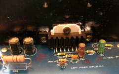
PowerAmp section Photo:
P.s. Can I upload more than 1 photo with 1 post?
Very interesting thread for me 🙂
Here is the photo of transformer in my 340 (non SE):
Do You think it's fake specs?
By The way. Non_SE 340 has 2*6800 Caps in PS, and I compared my 340 and Harman AVR-347 Receiver + PS3 + MA RS6. CA realy has bass leakage... 340 has more accuracy on bass, but it's not so powerfull as Harman
(Harman has 2*12000uF on Power amp PS)
P.s. Mike, I think You need to replace C3 with ~ 2.2 uF at first. I ca't undestand why CA ingeeneers placed there such big Cap.
Then replace all the caps in signal path.
P.s. #2 What is the DC offcet value you have on Input and output of the amp ?
Transformer Photo:
PowerAmp section Photo:
P.s. Can I upload more than 1 photo with 1 post?
Attachments
- Status
- Not open for further replies.
- Home
- Amplifiers
- Chip Amps
- CA 340A SE LM3886 based amp - Upgrade advice please.