We machine Plexiglas with conventional mills all the time. I'd like to try the lazer. What kind of finished edge do you end up with.
as acrylic will cut via laser cutting machine, edges will be very sharp and elegant, so I'll use polishing machine... I'll use micro-fiber cloth polishing 😀 the final result will be a very nice-looking and clear and soft edge which seems like the surface of the acrylic 🙄
one easy way for polishing plexi edges is with a torch but can't recall the gas used (the flame temperature is important)!
haven't done it my self so if someone tries it please do it on a small scrap piece cause i am not sure if it leaves it crystal clear!
haven't done it my self so if someone tries it please do it on a small scrap piece cause i am not sure if it leaves it crystal clear!
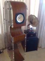
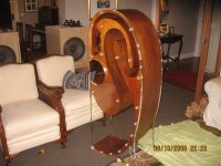
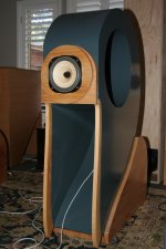
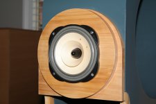
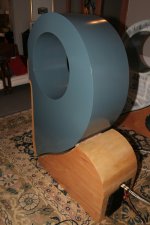
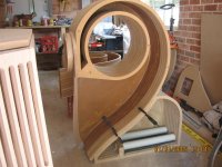
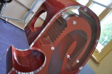
The shape below the driver is cosmetic, hence the C-horn name.
25mm (either German or Chinese) is expensive...I provision $500/side.
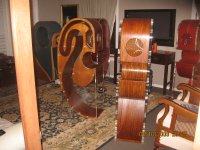
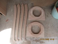
Cnc used for plexi...my cad file is modded for the acrylic shape, but holes align perfectly where the dowels fit...allows extra strength.
Edges are blow torched....not a DIY task...!
I've had lowther dx3, 206e's, and visaton b200's in the c-horn...all good.
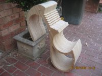
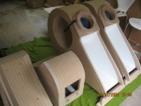
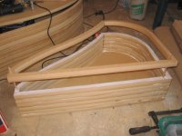
A mate just built the unit using birch ply...looks stunning with all the end grain showing.
I can't talk about providing/selling cad plans and cnc cutting files in the public, as this site is non commercial.
Hope this helps.
Andrew
25mm (either German or Chinese) is expensive...I provision $500/side.
Cnc used for plexi...my cad file is modded for the acrylic shape, but holes align perfectly where the dowels fit...allows extra strength.
Edges are blow torched....not a DIY task...!
I've had lowther dx3, 206e's, and visaton b200's in the c-horn...all good.
A mate just built the unit using birch ply...looks stunning with all the end grain showing.
I can't talk about providing/selling cad plans and cnc cutting files in the public, as this site is non commercial.
Hope this helps.
Andrew

I also build the Carfrae Little Big Horn under arrangement from Jim Carfrae.
While the C-Horn can be a DIYer's dream...the Carfrae cannot be sold as such.
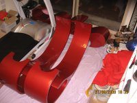
Lowther DX3 shown in this build.
Lowther 'Big Fun' horn and massive tapped horn shown in background of last pic. My lounge was being overtaken by horns...!!!
While the C-Horn can be a DIYer's dream...the Carfrae cannot be sold as such.
Lowther DX3 shown in this build.
Lowther 'Big Fun' horn and massive tapped horn shown in background of last pic. My lounge was being overtaken by horns...!!!
Attachments
Last edited:
The horn seems to have a very low mouth area.
Any idea what data to enter in Hornresp to get a prediction of bass performance?
Any idea what data to enter in Hornresp to get a prediction of bass performance?
The horn seems to have a very low mouth area.
Any idea what data to enter in Hornresp to get a prediction of bass performance?
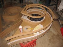
Mouth is 696mm x 320mm. Horn path is 2550mm. Throat is 44mm x 320mm.


25mm (either German or Chinese) is expensive...Iprovision $500/side.
Not surprised....
Not surprised....
I know...but, it's a high end speaker...so 'happy' to pay that.
Of course, the speaker can be made with MDF/ply sides...but you'd loose out on a lot of the aesthetics of the horn internals...which was always my design intentions.
Interestingly, I've thought of creating the Carfrae with acrylic sides as well.
It helps that I have a mate who's in the plastics business....still pricey though.
Kind regards
You can CNC acrylic.
I'm pretty sure that's correct. I remember seeing carbide bits specifically listed for plexi. To be certain the manufacturer of plexi itself could set you straight.
Andrew I have a few question, if you don't mind.
1) Why the change in the internal horn path from the CAD picture (Red/Smoke plexi) and your real picture (Red/Clear plexi)?
2) Which CNC version is the latest for cutting in two sections? Split in the speaker cutout (face) or split at the beginning of the "C" cutout (underside)?
3)How do you secure the plexiglass sides to the internals? Wood screws into the dowels?
Thank you for your time.
Andrew I have a few question, if you don't mind.
1) Why the change in the internal horn path from the CAD picture (Red/Smoke plexi) and your real picture (Red/Clear plexi)?
2) Which CNC version is the latest for cutting in two sections? Split in the speaker cutout (face) or split at the beginning of the "C" cutout (underside)?
3)How do you secure the plexiglass sides to the internals? Wood screws into the dowels?
Thank you for your time.
Hi.
1. No real reason. The CAD picture was the original mock up I created with the design engineer. When it came to the final workings, I opted for the current horn path. I guess the longer internal sections of the current design were easier to model.
2. The new design has the break below the comp chamber...refer to the pics of the all-ply version.
3. The side panels are designes to be fixed via large hex screws (eg 2.5 inches) directly into the hardwood dowels. The CNC cutting files have this all worked out.
It's a rewarding project for sure...but requires dedication and care...though it is straight forward. I've put a fair amount of thought into the design for the DIYers.
Kind regards.
Andrew
2. The new design has the break below the comp chamber...
Just to be anal, the compression chamber in a BLH is the room, the volume behind the driver before the throat is the Air Cavity.
dave
Just to be anal, the compression chamber in a BLH is the room, the volume behind the driver before the throat is the Air Cavity.
dave
Thanks.
I come from China, I also like the box, can share some of your drawings?E-mail 44220806@qq.comMy mate's ply version...
Can anyone tell something about Qurve back loaded speakers family ?
qurve | models
They look as much atractive as C-horns do.
Does the total length of folded horn fit to the suggested drivers in every example ?
qurve | models
They look as much atractive as C-horns do.
Does the total length of folded horn fit to the suggested drivers in every example ?
- Status
- Not open for further replies.
- Home
- Loudspeakers
- Full Range
- C-Horn Project!