Hi all,
Most of calculations for output trans on WWW mostly use EI core, I wish to know if anyone of you know how to calculate the c core SE output transformer?
Normally EI core with 14 cm square of center cross section area will handle 10 Watts SE down to 25 Hz with no problem, but if we optain c core with the same cross section area, it will be 3~6 times bigger than EI core which is not quite logic. ( look at those Lundahl with small iron but perform well)
Anyone can explain this?
BigBulb
The equations are the same for strip C-core and E-I laminations..
For the same given cross sectional AREA , you just need to see what the magnetic path length is for that core.... I don't recall there being a 3~6 times increase in size....then you refering to a larger core???
Give specific examples for clarification...such as lamination sizes and C-core sizes that you are comapring...
Chris
Hi,
I'm refering to the core size. For example, I have a push pull EI transformer rated 30 watts and the core cross sectional area is 11 cm square , ( 3.2 cm X 3.5 cm) using EI 96 lamination.
I have a pair of faulty double C core push pull output trans, I measured the core cross sectional area and it is only 5 cm square. ( 2.5cm X {1cm + 1cm}, double core ) This double C transformer is rated 35 Watts. If I choose double C core that have 11 cm square of cross sectional area, ( from some manufacturer's data sheet) The whole transformer size will be 3~ 6 times bigger than the actual 35 Watts double C core trans.
If I follow the calculation , 11 cm square of core size will give 30 Watts in pusshpull is about right but if I calculate the power rating for 5 cm square of cross sectional area, it only 6.5 watts for push pull,
This shows C core gives more efficient and smaller core size can give higher power rating, that's the problem, I don't know how to determine the C core power rating.
Please Help!!
Regards,
BigBulb
OK....Now I see what the problem is...
To explain this in full detail would be very long winded...I will keep it brief...
You really can not compare the two transformers...without knowing way more data...and it has nothing to do with C-core or EI laminations...
You can not corelate wattage to the core size....some books do this, but it is really incorrect, unless you are using the same standards for both transformers....
Manufacturers, do not all use the same STANDARD for defining the power output of thier output transformers...
The designer chooses this at will...
When I rate my OPT's I rate them at 20 HZ and at flux density of 12,000 Gauss...
While another manufacturer will rate thier power output at 400HZ and at 16,000 Guass....
This will produce totally different power levels for a same size given core... The later will show a higher power output for advertising hype but at the expensive of higher core distortion...
If the core material is different , then all bets are off, but usually 95% of output use M6 material...
One company may choose to use 1200 CM/A wire gauge while another may use 600 CM/A ...thus yielding more window area, allowing more turns, thus a lower flux density, lower core distortion and better inductance...at the expense of more copper losses which makes the audio less open and less clear sounding..
ANother consideration is the plate load...the larger the plate load then the bigger the AC plate volatge produced, this a larger flux density..therefore you need more turns...BUT the larger plate load for the same Wattage will have less current, thus a smaller wire gauge is used, therefore you better fill the window...
Also...the required inductance for a given plate load for THE SAME -3dB low frequency pole will be different....so this plays a big role as well.....and what are the different magnetic path lengths for these given cores....this also affect the L.....
So..... You need to examine transformers on a case-by-case basis from top to bottom before comparing them to each other...
Chris
Hi,
Thanks for your info, I will experiment with those C core, and I had been told that was M5 0.30mm which is lower loss than M6.
Thanks.
Regards,
BigBulb
Thanks for your info, I will experiment with those C core, and I had been told that was M5 0.30mm which is lower loss than M6.
Thanks.
Regards,
BigBulb
Hi ,
I had read this before, I have a question regarding this page, The C core cross sectional area is f1+f2, is that true? or just only one side?
regards,
BigBulb
I had read this before, I have a question regarding this page, The C core cross sectional area is f1+f2, is that true? or just only one side?
regards,
BigBulb
If your using a double C-core...then yes, you add up the AREA from both....
To be honest, that web-page about transformers is totally messed up....that is NOT how to design a SE transformer...
There are many considerations...here is just a quick look at a few things and is in no way complete...
The first thing you need to do is figure what plate load you need, then at what DC current is your DC idle current...
Then based on the plate resistance of your valve and the expected frequency response..you calculate the needed inductance, leakage and capacitance as your target goals..
You choose a winding geometry, interleaving, that works the best.... Too many interleavings of Primary and Secondary can be bad...there is an optimum geometry...
You then choose your maximum flux density...lets say 13,000 Guass to occur at 20Hz and at full power output...
For SE output transformers... you have to deal with the sum of your DC flux density and your AC flux density..... The more turns of wire, then the more DC flux density goes up... while AC flux density goes down... for starters set transformer Flux to be split evenly between the AC and DC flux..so make each at 6500 Gauss.. ALso remember that you need to do the negative air-gap method to calculate the proper gap to get the required inductance considering the turns and core area... It's all a balancing act ......
Choose your wire gauges between 800CM/A and 1000CM/A for primary and 600-800CM/A for secondary...
Chris
Hi cerrem,
Thanks for your info. I had calculated a 2 watts output for my 6C45 SE amplifier, and the primary result is 6200 turn for 4Kohm primary if I use 12.5X16X40 c core, I never seen a SE transformer have so many turns for primary, 3000 turns at the most. Some says c core need more copper for that reduced iron, is that true? 6200 turns for primary is correct? or I calculate it wrong?
Regards,
BigBulb
I can assist you with this transformer design...
I need to know EXACTLY what core you have..
Can you measure the Hieght and Width of the surface of the gap... is that the 12.5?? and the 16cm numbers ???
Is 40cm the legth of the entire two halves of the C-core when they are butted together???
What is the intended goal ?????
What would you like to make???
A headphone amp???
Do you prefer to go SE or Push-Pull???
Usually with SE amps...you want to take advantage of high voltage tubes.... Thats why transmitting tubes are popular...
The reasoning is that you want to keep the DC current low but want to produce the most WATTS..so you compensate for the low DC current by using high DC voltage...
Chris
Hi cerrem,
Thanks !
I have two types of c core, one is M5 0.30mm material and diamention for the gap surface is 12.5mm X 16mm, and the length is 40mm when two halfs of c core butted together . Magnetic path length is 14.9cm. It weights 0.24KG for a half piece.
another type of C core is same material, but bigger size at 12.5mm X 25mm X 60mm. magnetic path length = 19.7cm. The weight is 0.47KG for a half piece.
I want to try a smaller one first, to get winding experience and it might suite interstage winding ( future 845 project)
The OPT I'm going to wind is for a 6C45pi single ended , with 4Kohm primary and 8 ohm secondary. the core size seems can handle 2 watts ( 6c45 only gives 1.2 watts or so at clipping point) previously I calculated the primary of 6200 turns is for 25Hz at -1dB point, and DC current will be at 45mA.
Thats the spec for my first transformer, and the bigger core might keep for my future 845 SE projects. if the core size is suitable.
I have 2 sets of winding machine , (from surplus sales) one motorised and another is hand crank with an automatic arm to hold the copper wire to tidily wind on the bobbin.
Hope you can help me to calculate the OPT, Thank you.
Regards,
BigBulb
OK..this helps...but it is still not enough...
These numbers don't match up with earlier number you provided... Where did you get the magnetic path figure???
12.5mm x 16mm = 20cm squared for the AREA ... must multiply by stacking factor for "effective" AREA...use .92 for now...
Now that is for a single C-core type of transformer....which consist of two halves...
Earlier thread you mention using DOUBLE C-core for your transformer... this would be 4 halves....and your area would be 40cm squared... SO which core set up are you planing to build??
Are you set on using the 6C45 ???
ARe you set on doing Single Ended???
Were these cores previously used in Push-Pull application..???
ARe the mating surfaces of the cores lapped smooth???
If you can trace out a core on paper then Email it to me..
It is important for me to see all the dimensions, since the inside dimensions are critical to setting up the bobbin size..
I assume 16mm is the Height of the C ???
Setting up the GAP will be a pain...you will have to rig up a set up that puts a DC current into the primary as well as a superimposed AC voltage..The adjust the gap for a target AC current at a specific DC current...this will insure you have the targeted inductance adjusted correctly...we will jump off that bridge when we get there....
Are you committed to doing this as Single Ended???
A Puh-Pull version would be a heck of a lot easier and put out a bit more power...
Once I get the full core data..i will crank out the numbers....
What is the intended application????
Chris
Hi,
I'm not using old core that I mentioned at the first post , that is for a push pull trans.I just use it as comparison, but my new design will use new C core.
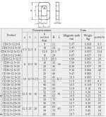
The two types of c core are new core that I purchased from transformer lamination manufacturer. The manufaturer did mentioned effective AREA around 0.92 thats right. Now I need a OPT as shown below:
M5 0.30mm material
Single C core 12.5mmX 16mm X 40mm
Single ended 1 x 6C45pi, single stage power amplifier,( driving coral Beta 8 speaker.)
4Kohm : 8 ohm
the core surface is smooth since it is new one.
The dismention is as below:
Regards,
BigBulb
I'm not using old core that I mentioned at the first post , that is for a push pull trans.I just use it as comparison, but my new design will use new C core.
The two types of c core are new core that I purchased from transformer lamination manufacturer. The manufaturer did mentioned effective AREA around 0.92 thats right. Now I need a OPT as shown below:
M5 0.30mm material
Single C core 12.5mmX 16mm X 40mm
Single ended 1 x 6C45pi, single stage power amplifier,( driving coral Beta 8 speaker.)
4Kohm : 8 ohm
the core surface is smooth since it is new one.
The dismention is as below:
Regards,
BigBulb
Attachments
OK...That was great info...
You still need to tell me if your using a single C-core arrangement or a Double C-core arrangement...look at the attached photo and tell me wich one you plan on doing....
.92 is not the AREA...it is the Stacking Factor... This should be very close to what it is....
Does the manufacturer say what the "effective" AREA is???
It's gotta be close to 18.4 cm squared.....
DO you already have a bobbin???
The reason I need to know proper numbers is to do this design correctly.... The inductance, the GAP, The DC flux desnity all are inter-dependent on each other...and need to solve simulataneous equations to satisfy all the conditions set forth...
Chris
Attachments
cerrem said:...12.5mm x 16mm = 20cm squared for the AREA ... must multiply by stacking factor for "effective" AREA...use .92....
Isn't 12.5mmx16mm= 2 cm squared?
YES!!!
Thanks....I am not thinking straight....
12.5mm x 16mm = 200mm squared = 2cm squared
OK....thank You....
Chris
BTW: I looked at the curves for the 6C45pi...I can't see how you get 1.5W under your conditions of 45mA at 4K load ?????
Unless you plan on going into A2????
The MAX plate voltage is 150V...
Max plate dissipation is 7.8W.....
I attached the curves..
Attachments
Hi,
The 6C45pi can't get 1.5 watts. I build mine supply B+ with 215 volts and plate current at 40mA , plate dissipation 8.6 watts ( this tube can take a lot of abuse...) and already run for a year ,listen to it everyday. Currently I'm using Hammond 125ESE and my scope show clipping at 8.6V Pk-Pk into 8 ohm resistive load at 1 Khz. That gives around 1.2 watts of output. I wish to have the OPT design that can handle 1.5 to 2 watts, more headroom for it, if possible. The amp is a single stage amp, CD player output directly goes to grid of 6C45.
Sorry I didn't mentioned it clearly, 0.92 is stack factor,Manufacturer says " times 0.92" actual AREA is 1.84 sq/cm.
I'm not using double C core:
SINGLE C core 12.5mmX 16mm X 40mm (NOT DOUBLE C CORE)
Single ended 1 x 6C45pi, single stage power amplifier,( driving coral Beta 8 speaker.)
4Kohm : 8 ohm
I build the bobbin myself, I always rewind EI transformers for my friends so a handmade bobbin is not a problem.
I also have copper wire range:
0.05mm, 0.15mm, 0.19mm, 0.22mm, 0.335mm, 0.5mm, 0.8mm, 1mm
so copper wire also not a problem.
Thanks for your help.
Regards,
BigBulb
OK...
Here are the basics....
using a bobbin of 1.5" width.... use .02" marging on each side of bobbin.. use a .05" thick bobbin...
Youwinding width willbe about 1.316"
You will need 7248 primary turns... use 1mill insulation between primary layers...
39 layers....188 turns per layer of #34 AWG (.007" single coat).. spiral last layer...
The Gap is .02676...so you have two gaps....so each surface on the C-core will have a .0134 gap....
The inductance will be 17.5H ...this will have a -3dB at 11.3HZ....
Total Flux Density at 1.5W is 13,000 Gauss which is .66% core distortion at 20Hz....
The primary winding resistance is roughly 630 ohms...
The secondary would have 324 turns ......5 layers of #25 AWG...69 turns per layer...spiral last layer..
How you split up these layers is KEY....
3 primary sections and 2 secondary sections would have 47mH leakage....not good enough....
You need 4 primaries and 3 equal size secondaries...
The size of the two inner primaries need to be twice as big as the out 2 primaries..
Chris
Here is the BODE plot for above transformer...
The Inductance is 17.5 H with each gap is set to .0134" ....
The Leakage is 19.8mH....
The total Capacitance is 1820pF...
All Primary sections are in series...
The 3 secondary sections are in parallel..you could of course use a bigger gauge of wire in the secondaries..I leave that to yo to fit...
The Inductance is 17.5 H with each gap is set to .0134" ....
The Leakage is 19.8mH....
The total Capacitance is 1820pF...
All Primary sections are in series...
The 3 secondary sections are in parallel..you could of course use a bigger gauge of wire in the secondaries..I leave that to yo to fit...
Attachments
- Status
- Not open for further replies.
- Home
- Amplifiers
- Tubes / Valves
- C core output design