This is an offshoot to a discussion from Lhquams Balanced F5 thread. The benefits of eliminating the source resistor in an F5 are well understood now and covered in the F5 turbo and F6 articles and I'm sure in many other places. The diode shown in the turbo thread is one way of getting square-law benefits while also keeping the DC bias stabilization benefits of the source resistor.
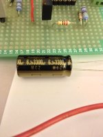
Another way is to bypass the source resistor with a capacitor. Because the voltage dropped across the resistor is small, we can try paralleled high-capacitance low-esr parts. These low voltage caps are commonly used on PC motherboards so are cheap and plentiful. The sims below try and show the approximate effects on freq response and thd for a F5 driven at high outputs with and without the caps. The schematic is the standard F5 and the asc below is one I pulled from one of the threads here some time ago. The models are all embedded so that it's easy to run for anyone interested.
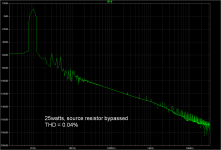
What are the effects with 2x 3300uf of the 6.3v low-esr caps, at 40v pk-pk into 8r (ie abt 25watts) ?
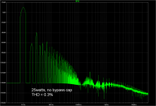
First are the distortion results with and without the caps.
Without caps: THD is 0.3%, distortion spectra as shown.
Then with caps: THD is 0.04% as the square law effect kicks in to give us more class A operation.
Another way is to bypass the source resistor with a capacitor. Because the voltage dropped across the resistor is small, we can try paralleled high-capacitance low-esr parts. These low voltage caps are commonly used on PC motherboards so are cheap and plentiful. The sims below try and show the approximate effects on freq response and thd for a F5 driven at high outputs with and without the caps. The schematic is the standard F5 and the asc below is one I pulled from one of the threads here some time ago. The models are all embedded so that it's easy to run for anyone interested.
What are the effects with 2x 3300uf of the 6.3v low-esr caps, at 40v pk-pk into 8r (ie abt 25watts) ?
First are the distortion results with and without the caps.
Without caps: THD is 0.3%, distortion spectra as shown.
Then with caps: THD is 0.04% as the square law effect kicks in to give us more class A operation.
Attachments
Last edited:
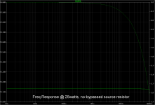
The caps give us some rolloff at low frequency... -0.2db at 10Hz vs flat as a pancake for the stock F5.
The sims aren't definitive of course and my own sim skills are wanting but overall impressions seem to square up with logic.
IMHO, a worthwhile thing to try in a stock F5 build since its completely reversible but I would stay away from going nuts with the amount of capacitance since it increases the time that it would take for the DC across it to build and so for the bias to stabilize. Till that cap is charged the bias will shoot thru the roof - so maybe 3300uF and then add another if things are going ok ?
Buzz I think has tried it so mebbe he can clue us in as well...
Attachments

Last edited:
Firstly, in our experience, no known device we have measured obey straightly the square law.
Secondly, I think you should try to model a 3300µF (electrolytic ?) cap with sime ESR and internal inductance.
Thirdly I suggest you do some reading on distortions to AC signals in caps, especially electrolytics.
I think even most tube guys these days try to avoid using a cap to bypass the resistor at the cathode ?
I wonder why ......
🙂
Patrick
PS
LT Spice is only as accurate as the model you use to do the simulation.
It is a useful tool, but not exactly reality.
...
I think even most tube guys these days try to avoid using a cap to bypass the resistor at the cathode ?
I wonder why ......
🙂
......
exactly ;
idea is worth thinking ........ but just that ......
The voltages involved, amounts and type of feedback used in valve amps vs the F5 bear thinking about. It needs to be emphasized also that if your amp/speaker/volume levels means that you never, ever leave class A even on peaks, as-is, then this line of inquiry above does not have much, if any, value.
Will try practical results and report hopefully in a week or so but I can't see why it won't work along the lines above.
Patrick, I did sim with the derated ESR but could not find any guidance on inductance value in the data sheets - let me know indicative values if you have some clues.
Thanks to you both for the pointers.
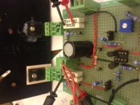
did not want to post the asc until i could attribute the file to its source.
Here is where i got the original iirc: http://www.diyaudio.com/forums/pass-labs/157174-f5-spice-simulation.html#post2021747. I yanked out all the protection circuitry etc in the orig schem .....
Any mistakes left are of course my own 😀 cheers,
Here is where i got the original iirc: http://www.diyaudio.com/forums/pass-labs/157174-f5-spice-simulation.html#post2021747. I yanked out all the protection circuitry etc in the orig schem .....
Any mistakes left are of course my own 😀 cheers,
Attachments
Last edited:
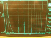
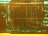
THD spectra - far and away less dramatic than the sim 😀
Ok ... so what did we find... thd drops with the caps (from 0.084% to 0.049%) and ....
interestingly something funky happens to the h2/h3 balance!
Check out the detailed results:
No bypass caps; then WITH bypass caps
thd: 0.084; 0.049
H2:-69.8; -65.8
H3:-52.5; -59.6
H4:-91.93; -88.5
H5:-72.33; -74.8
So adding the bypass caps reduce overall measured thd but shifts thd balance in favor of H2 😕
Dunno why this is the case, maybe the caps are not exactly equal in value and caused the added H2 ?
But anyway what we should see is reduced distortion by adding the caps and a subtle shift in H2/H3 balance that may suit your tastes or otherwise.
Also I dunno how much of the effect is due to square law and how much is just due to more gain from the output stage.
Not a trifling reduction nonetheless from just adding two cheap passives....
cheers
Attachments
Last edited:
In this circuit bypass caps increase open loop gain, more feedback, less
total thd. The Source resistances suppress the differences between N and P
channel, so greater 2nd/3rd with bypass caps.
😎
total thd. The Source resistances suppress the differences between N and P
channel, so greater 2nd/3rd with bypass caps.
😎
I'm getting less h3 with cap but more h2 - can that be due to more olg, more fb effect ?
Also the outputs here were both n channel (post 8) but I don't think that changes your conclusions any
Also the outputs here were both n channel (post 8) but I don't think that changes your conclusions any
I guess you would need to post the schematic, but I still expect that there
is asymmetry in the circuit being suppressed by the Source resistors.
😎
is asymmetry in the circuit being suppressed by the Source resistors.
😎
Your guess is right i reckon - i did not match the fets nor trim h2 at all so theres likely assymetry between top n bottom halves.
The schem - is roughly the one here with source resistors and irf outputs: http://www.diyaudio.com/forums/pass...regation-pass-inspired-ideas.html#post3355004
The schem - is roughly the one here with source resistors and irf outputs: http://www.diyaudio.com/forums/pass...regation-pass-inspired-ideas.html#post3355004
In this circuit bypass caps increase open loop gain, more feedback, less
total thd. The Source resistances suppress the differences between N and P
channel, so greater 2nd/3rd with bypass caps.
So is the apparent decrease in distortion a function of the cap doing something to the circuit's linearity,
or just because of the increase of total feedback?
The reduction in H3 is likely increase in feedback. The relative increase in
H2 is likely decreased symmetry without degeneration.
😎
H2 is likely decreased symmetry without degeneration.
😎
I know this post is a bit old but I am curious what the outcome would be if your test circuit had a p3 to balance the distortion after the additional caps.
P3 can null out H2. So the combined effect of a P3 and bypass caps should be further reduced THD numbers.
sorry can't help there - I don't have a live F5 handy. I think i caused some confusion - the title of this thread was intended for the sim example shown earlier on. The measurements were done on another push-pull amp (see post 8). Nelson in post 16 explains the results nicely and I agree completely.
All that said, i have been using the bypass caps for some time and love them. I drop the loop feedback a touch as well while i'm at it. Opens up the sound a lot.
All that said, i have been using the bypass caps for some time and love them. I drop the loop feedback a touch as well while i'm at it. Opens up the sound a lot.

- Status
- Not open for further replies.
- Home
- Amplifiers
- Pass Labs
- Bypass caps on source resistor (F5 example)