Having truble with an amp that was recently handed down to me by my brother (chrome Rockford Fosgate 250.2). When turned on the power supply makes a buzzing noise and then blows the 60 amp fuse at the battery javascript:smilie(' '). Yesterday i looked under the hood and the board looks flawless, no burt traces or components. What givesjavascript:smilie('
 ').
').
'). Yesterday i looked under the hood and the board looks flawless, no burt traces or components. What givesjavascript:smilie('').If it only blows the fuse after the remote voltage is applied, it probably has shorted output transistors or someone has gone in and turned the bias up too high.
Disconnect all speaker wires from the amp and disconnect the RCA jacks. Replace the fuse with a 15 amp fuse. If the fuse blows when you turn the head unit on, the amp is the problem. If the fuse doesn't blow, you need to check the wiring.
If the fuse blows and you want to troubleshoot the problem, disconnect the amp and remove the bottom cover. The output transistors are connected to the large green resistors.
Measure the resistance from the middle leg to the third leg of each of the output transistors, If you find any group (3 transistors per group) that appears shorted, at least one of the group is shorted.
You can generally determine the shorted one by measuring the resistance from the first leg to the middle leg. The one with the lowest resistance is the shorted one. If you cut it out of the circuit (all 3 legs), you may be able to get the amp to power up to determine if there are any further problems.
Heres the pic. I installed it where my previous amp was so wiring is ok, ( I double checked). It blows the fuse when +12V are applied to the remote turn on. Trubleshooting on an amp this complicated would take some time and my sodering skills are not that great so I was considering paying someone to do it for me. Reason being I don't have the equipment necesary to test and properly diagnose such problems. Who would you guys and gals recommend that does a good job at a fair price?? And by the way thank you Perry for the info, I kinda decided not to fix this paticular one becouse I have my old and not so expensive cunch amp that could be used for practice.
You can check the output transistors with a $10 digital meter, that is all you need. They are the ones clamped to the heatsink and usually not near the round transformer, those would be the power supply transistors.
Where could I get the IRF540's? Should I replace all of them? What do you recomend??? I tested all of the IRF540's with my friends Blue Point meter and 4 IFR540's are shorted. Are there any other devices to check or measure while i have the meter? Sorry, you can tell im kind of new to this but what the heck maybe ill lear a thing or 2. I'll try to post some pictures as soon as figure how to. Thank U, and by the way Merry Christmas to all of you!
I'll try to post some pictures as soon as figure how to. Thank U, and by the way Merry Christmas to all of you!Yes, while they were on the board my meter read 1.00 witch means no continuity between terminlas 2 and 3 of 4 IRF9540's. The rest of them had continuity between terminals 2 and 3 (are they still good?) When compared to another Rockford 250.2 from Amp Guts website, I noticed that one diode is missing on the left side of the transformer labeled D101😱. I assume D101 is a diode, am I correct, if so what is it's function? Thank U for being patient.
When compared to another Rockford 250.2 from Amp Guts website, I noticed that one diode is missing on the left side of the transformer labeled D101😱. I assume D101 is a diode, am I correct, if so what is it's function? Thank U for being patient.When your meter is set to ohms and you touch your meter leads together, does the meter read 1.00? If not, what does it read?
Or does the meter read 1.00 when they meter leads are not touching?
Set you meter to ohms and re-check the transistors. Post the circuit board designation number (Qxxx) and the resistance from legs 2 to 3 for each of the IRF9540s.
Or does the meter read 1.00 when they meter leads are not touching?
Set you meter to ohms and re-check the transistors. Post the circuit board designation number (Qxxx) and the resistance from legs 2 to 3 for each of the IRF9540s.
It appears that this amp may be the same as a 250m2. If that's the case, D101 is the same as D100. Both are a 1N5366B.
When I set the meter to ohms it buzzes and reads .000 meaning there is continuity between the touching leads. When there is no continuity it reads 1.0. The only info on the board reads PC-0767J , J. Welch and I guess the serial number attached B19QA8A001296. I noticed that there are 12 fets, (6 one side and 6 on the other). The las 3 on each side have part # IRF9540 and the others have Part #IRF540. Herer are the #'s starting from top left to right IRF540- .004 IRF540- .004 IRF540- .004 IRF9540- 1.427 IRF9540- 1.425 IRF9540- 1.418 Starting from left to right on bottom IRF540- .002 IRF540- .002 IRF540- .002 IRF9540- 1.417 IRF9540- 1.415 IRF6540- 1.421 Prob. getting a new Weller WP35 for soldering, my 7200 series is harder to work with. I read your web page Perry, filled with usefull info about amp repair. This amp defenetly has been worked on, hopefully I'll get it running
OK, 6 of the 540s are showing a short. Measure the resistance between the first leg and the second leg of the 540s. If one of each group reads significantly lower than the other two in the group, it's the defective one.
If there is only one defective one in each group, you can cut ALL 3 legs of the defective one free from the board and the amp should power up (if the supply isn't blown). This will tell you if there are other problems.
Remember to power it up through a 10 amp fuse.
If there is only one defective one in each group, you can cut ALL 3 legs of the defective one free from the board and the amp should power up (if the supply isn't blown). This will tell you if there are other problems.
Remember to power it up through a 10 amp fuse.
While taking the mosfets out, I "accedentaly" pulled a few of the solder holes along with a tiny peice of plated through hole trace. And now when trying to install new fets the there is nothing where to solder them to. Is there any repair holes i can purchase and istall myself? Also, after reading a few posts, when replacing burnt fets is it a good idea to replace the resistors? If so what is the value? Please advise thanks.
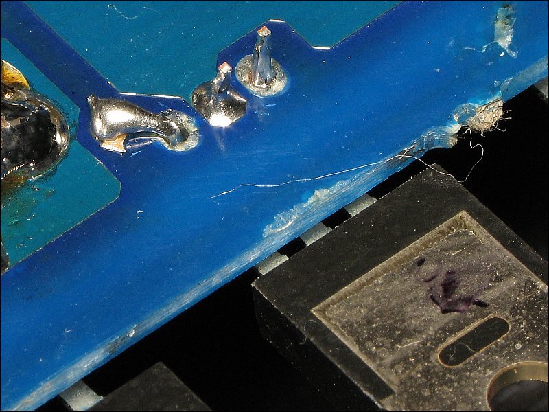
Are the legs on the fets long enough to wrap around to the trace? If not you could solder some bare wire from the trace to the legs. Not pretty but it works in a pinch.
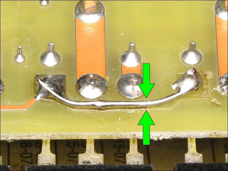
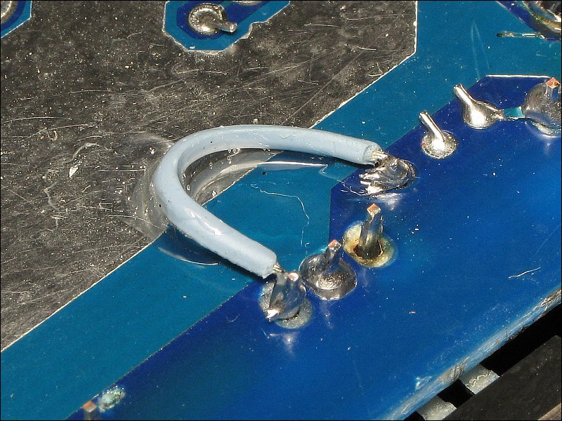
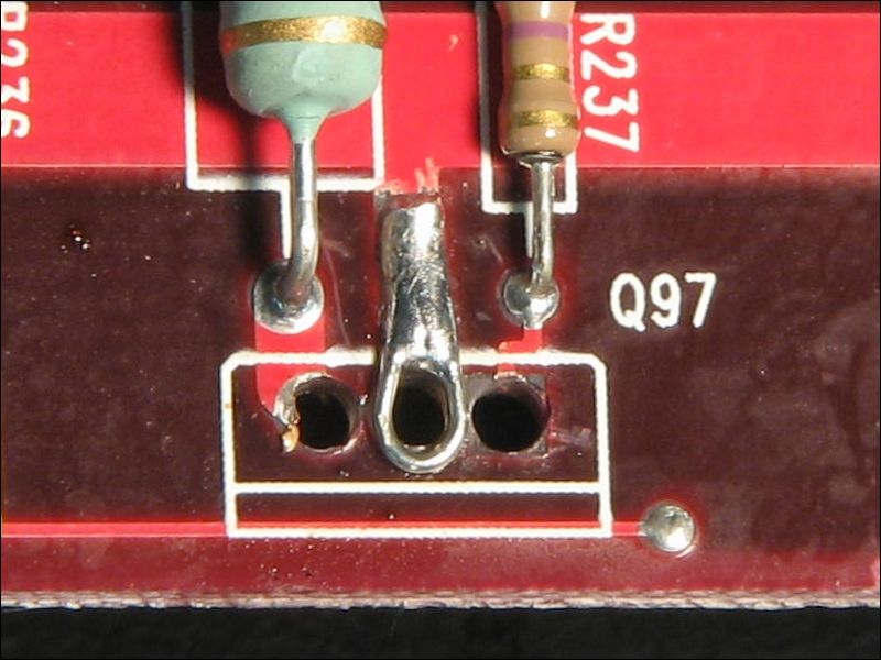
Any of the following will provide reliable connections. If the broken connection is between the FET and a surface mount resistor, you should use a small flexible wire so no stress is put on the SMD pads. The insulated wire below is from a computer IDE cable. It works well for low current connections. Using a drop of adhesive to hold the wire will prevent the wire from breaking (in case the amp is subjected to heavy bass/vibration). For connections that will have to pass significant current, you will need to use something that can handle more current than the insulated wire shown. The method used on the red board below is suitable for high current.
To post photos, you can use the browse button below. There are strict limitations on size (file size and dimensions). If the file is too large, you will receive an error message. If you get the error message, there's a good chance that the message will be lost. Either post the photos and text in separate messages or copy and paste the text of the message into a text editor before submitting so it's not lost.
The photos above were uploaded to a server. I used the IMG button to insert the URL of the images. You can do this with various photo sites (flicker, photobucket, shutterfly...).
FET Test curcuit / curcuit board
Perry showed some nice pictures of how you can install the transistors and make the connections if the lines are broken. If there was no chance of fixing the lines Perry showed you can cut out a small part of the curcuit board completely and insert (using heat resistance glue) a small part of standard printed curcuit board from Radio Shack.
If you have your mosfets out off the curcuit board you can test the N-channel FETs with the following curcuit. (For P-channel FETs switch the diode next to the relay, the LED and also switch polarity of the power supply)
An externally hosted image should be here but it was not working when we last tested it.
- Status
- Not open for further replies.
- Home
- General Interest
- Car Audio
- Buzzing noise on RF 250.2