I know this is not about an amplifier really, but I need some help with the design of a simple circuit if someone is feeling kind.
I have a thermistor in my car that measures air temp going to the engine. How can I make a circuit that buzzes when the resistance drops below 500R? I want it to let me know if my car is running too hot.
Thanks so much!
I have a thermistor in my car that measures air temp going to the engine. How can I make a circuit that buzzes when the resistance drops below 500R? I want it to let me know if my car is running too hot.
Thanks so much!
The buzzer itself can be a real buzzer such as used for a doorbell. Or it can be something like a 555 timer connected to a speaker.
The sensor needs to connect to the thermistor without disturbing the present circuit and matched to a comparator that has an adjustable threshold, which in turn enables the timer or the buzzer.
Concept simple, execution a bit of a project.
The sensor needs to connect to the thermistor without disturbing the present circuit and matched to a comparator that has an adjustable threshold, which in turn enables the timer or the buzzer.
Concept simple, execution a bit of a project.
Use a thermistor to sense temperature as one leg of a resistive divider, and a comparator to set the trip point, an LM311 would do just fine with a cheap reference and a pot to set the threshold. There are lots of 12V piezo buzzers available that can achieve sufficient (sometimes way too much) spls to get your attention. These parts should be available from a variety of online sources, RS Components or Farnell.
Edit: The LM311 is open collector and will run most piezo buzzers directly off of 12V. The thermistor would be connected to the - input of the comparator and the adjustable reference voltage to the + input. Some hysteresis to the + terminal from the output is advisable, a 1M resistor would probably suffice.. Look at the app notes for the LM311 for suitable circuits.
Edit: The LM311 is open collector and will run most piezo buzzers directly off of 12V. The thermistor would be connected to the - input of the comparator and the adjustable reference voltage to the + input. Some hysteresis to the + terminal from the output is advisable, a 1M resistor would probably suffice.. Look at the app notes for the LM311 for suitable circuits.
Last edited:
Digging up this thread as I've got the bits now.
Sorry to be thick, but what should I do with the Balance/Strobe and Balance pins on the LM311?
Also, what is the best way to run this device from a car battery, given it is a dual-rail device? I've seen single supply application circuits for the LM4780 chip amp for example, and from what I see it basically runs the negative rail by taking the positive supply, putting it through a voltage divider and then feeding that to a pass transistor. Is it that simple, basically lift the negative rail up to half of the positive? The application I'm looking at also has some input bias current on the amps inputs, but am I right that I don't need such things with the voltage comparator?
If some kind soul could actually draw this noob a circuit for making such a buzzer run, it would be much appreciated!
Last edited:
Digging up this thread as I've got the bits now.
Sorry to be thick, but what should I do with the Balance/Strobe and Balance pins on the LM311?
Also, what is the best way to run this device from a car battery, given it is a dual-rail device? I've seen single supply application circuits for the LM4780 chip amp for example, and from what I see it basically runs the negative rail by taking the positive supply, putting it through a voltage divider and then feeding that to a pass transistor. Is it that simple, basically lift the negative rail up to half of the positive? The application I'm looking at also has some input bias current on the amps inputs, but am I right that I don't need such things with the voltage comparator?
If some kind soul could actually draw this noob a circuit for making such a buzzer run, it would be much appreciated!
Ignore balance and balance/strobe pins. The LM311 is well suited to single supply operation and in fact is often used that way. I'll try to post something for you tomorrow morning. (my time)
Please post all of the electrical information you have for the thermistor you have, and the desired trip point in degrees C.
Given any thought as to how you are going to calibrate it? I suggest you will need a reasonably precise oven thermometer, and a gas or electric oven I would think. 😀
Last edited:
You dont even really need an opamp, a transistor will do. Get a buzzer thats got a built in oscillator (so you just supply 12v to it), theyre cheap enough.
The thermistor is RS part number 697-4553. It needs to trip when the thermistor value drops below 500R which is about 90c. I've got a buzzer with a built in occilator, so it just needs to output some voltage when the trip point is reached.
Would this work?

Would this work?
Yes a basic opamp comparator circuit would do the job. You'd likely have the reference voltage adjustable by a trim pot so that you can set when the buzzer will sound.
One small catch, in a car, 12V is not always 12V. If you connect the opamp directly to the car's 12V supply, it will eventually die due to spikes causes by load dump situations from the alternator. There are voltage regulators designed for automotive use that will take care fo this.
One small catch, in a car, 12V is not always 12V. If you connect the opamp directly to the car's 12V supply, it will eventually die due to spikes causes by load dump situations from the alternator. There are voltage regulators designed for automotive use that will take care fo this.
set up the Vref string and the Thermistor string as a measuring bridge using the same +12V and 0V tappings. This removes voltage variations from the comparator functionality. It compares thermistor resistance to reference resistance.
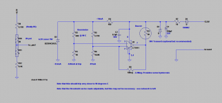
As promised here is what I would do - should work with any bogey variety LM111 - 311 or the LT1011..
I prefer to operate the thermistor and reference string off of a lower voltage in order to avoid potential input common mode range issues, although in this case device CMR is sufficient for operation directly on the supply. Being relatively ratio-metric as shown a regulated supply is not is not strictly necessary, but 1 watt 6.2V zeners are quite cheap. Depending on the degree of precision required you might not even have to calibrate it. (Depends on the accuracy of the thermistor) The lower voltage is preferable I think in order to reduce internal self-heating of the thermistor.
1% tolerance, low tempco resistors are assumed. Except as noted all may be 1/4W CN55 types or similar. Transorb/TVS diode is optional, but recommended - largely anything you can find in a through hole package should be adequate for this task. R7 should be 1W type, and I do recommend a 1A fast blow fuse ahead of all of this, and I assume this will be switched by the ignition switch as current consumption is significant. Non-destructive reverse polarity protection is included.
Buzzer current should be no greater than 50mA - if this is not the case a minor change is necessary to add a driver transistor. Most solid state buzzers I have encountered use less than 50mA so you should be OK.
Note: You could omit R4 and D2 and operate the thermistor directly on 13.8V supply if you wish. (I wouldn't..)
Attachments
Last edited:
Note that the measurement and reference resistors constitute what is commonly known as a wheatstone bridge if that helps you understand a bit better how it works.
- Status
- Not open for further replies.
- Home
- Amplifiers
- Solid State
- Buzzer circuit?