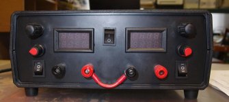
So if a load / psu is build for i.e 30V 30A and Insulation between terminals
and chassis / other terminals: is ≤60VDC, all should be fine?
Should be fine as long as none of the output terminals are grounded,
and proper polarity is observed when connecting them in series.
Oh, hmm... lets say two power supply's both of the same type, non of them grounded. What if I need -30V and +30V to drive an op-amp?Should be fine as long as none of the output terminals are grounded,
and proper polarity is observed when connecting them in series.
Oh, hmm... lets say two power supply's both of the same type, non of them grounded.
What if I need -30V and +30V to drive an op-amp?
That would be fine, it's the way most of them are used (series connection with the center used for the common).
Okay pew, thanks🙂That would be fine, it's the way most of them are used (series connection with the center used for the common).
Am I right in concluding that if isolation is 60V and both units is floating and can deliver 30V each, I can make 0V - 60V and -30V - +30V without any concern?
Okay pew, thanks🙂
Am I right in concluding that if isolation is 60V and both units is floating and can deliver 30V each,
I can make 0V - 60V and -30V - +30V without any concern?
Yes, lab supplies are used like this all the time.
fantastic, great:Yes, lab supplies are used like this all the time.
As I have said before, I do really appropriate your fantastic help!!
But we shoult check if such posibility is allowed for that exact power supply. Even if there isn't such possibility then it could be added with parallel (antiparaller) diodes.Yes, lab supplies are used like this all the time.
Okay, sorry but what / how are these diodes used?But we shoult check if such posibility is allowed for that exact power supply. Even if there isn't such possibility then it could be added with parallel (antiparaller) diodes.
It's just a powerful rectifying diode, connected between outputs of each power supply (between "+" and "-",). Of cause, diode must be closed (not open) by output voltage.
Oh in that way, thanks🙂It's just a powerful rectifying diode, connected between outputs of each power supply (between "+" and "-",). Of cause, diode must be closed (not open) by output voltage.
Maybe some sort of switch box and heat sinks to make change from 0-60V to -30V - +30V an easy task?
Yes, thanks. What I was thinking is if a diode shall handle many amp.Here is a very easy way to change (jumper):
While writing this reply, do I suddenly doubt what power I will get out of the sollution.
lets say two power suplys 30V at 30A, put in -30V to +30V configuration, do I then also get 60A?
If the psu's is in 0-60V do that also give 60A?
My reason for thinking about making a switch box, were that a diode with 60A, sounds like a lot of heat!! And instead of having to let the diode dangle in the air, why not build a simple alu box with a simple switch, and thereby just flicker the switch when I need to change the setup?
Diode rated current must be larger then power supply rated output current.Yes, thanks. What I was thinking is if a diode shall handle many amp.
Series connected power supplies have a rated current as in an only one.
Ok yes that sounds logical!Diode rated current must be larger then power supply rated output current.
Series connected power supplies have a rated current as in an only one.
Am I right in assuming that it is better to get a massive wary high current diode, gives less heat, so it is better to go over board when buying that diode?
How would the power supply's react the diodes voltage drop, do you not end up with i.e. a difference in ground at 1.6V?
- Home
- Design & Build
- Equipment & Tools
- Buy - "Noiseless" Electronic load
