Hello, I've managed to get started putting together the power supply of my BA3 using a 1500VA transformer 2x19V AC.
I want to verify the behavior of the supply under the worst possible load (I estimated a 15 A would be it)
I obtained a voltage drop that worries me at this load that is just 30% of the rated power; well within the de-rated limits (of ~750W)
So the voltage drop from 48V is more than 10 V with a continuous 15 A consumption.
I am now wondering if the transformer is really a 1500VA one or was a manufacturing mistake.
I used a very thick Ni-Fe wire for the load (1.5mm).
The power load is three times that of the estimated bias and this consumption would maybe be reached at clipping.
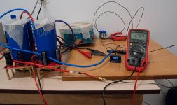
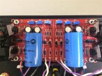
See attached picture.
This drop goes without saying is transformers fault since i was careful to use thick cables and the coil is ~200mOhm hence no power loss anywhere (I also went to 36 A consumption and the voltage lowered to 26V) But this case was pure curiosity and by no means a possible constant load.
Bottom line ; Will my BA3 work properly if it sees -10V on rails in its absolute biggest consumption moments that are not covered by the 2 x 150 000 uF CLC filter?
I want to verify the behavior of the supply under the worst possible load (I estimated a 15 A would be it)
I obtained a voltage drop that worries me at this load that is just 30% of the rated power; well within the de-rated limits (of ~750W)
So the voltage drop from 48V is more than 10 V with a continuous 15 A consumption.
I am now wondering if the transformer is really a 1500VA one or was a manufacturing mistake.
I used a very thick Ni-Fe wire for the load (1.5mm).
The power load is three times that of the estimated bias and this consumption would maybe be reached at clipping.
See attached picture.
This drop goes without saying is transformers fault since i was careful to use thick cables and the coil is ~200mOhm hence no power loss anywhere (I also went to 36 A consumption and the voltage lowered to 26V) But this case was pure curiosity and by no means a possible constant load.
Bottom line ; Will my BA3 work properly if it sees -10V on rails in its absolute biggest consumption moments that are not covered by the 2 x 150 000 uF CLC filter?
Attachments
Last edited:
How many devices are you planning to use in your amp? I’m curious how you ended up with a worst case load of 15A...
How many devices are you planning to use in your amp? I’m curious how you ended up with a worst case load of 15A...
I use a 2x19Vac transformer giving +-24V rail and expect 24 devices arranged in 4 channels unbalanced switchable to 2 channels balanced.
The amplifier load does not exist at this point but i wanted to test the supply under load.
I calculated the full bias to need 7.6A for 24 devices with .47 source resistors.
Upon finishing, on top of that when amplifying a 50Hz sine, for example, the amplifier will demand double the bias 7.6A. But at that point the rails will be +- 17.5V (total of 37V instead of 48V).
I did not expect a drop so big and am still curious why my transformer drops so low in voltage under ~30% rated power load(my main concern is a rating error).
How much voltage would be considered an acceptable drop under continuous load?
Last edited:
My issue is rather simple. After measuring the AC rails under load i noticed that there is no AC voltage drop.
The drop is seen after the rectifier and shunt capacitors and is not really a drop ; there are just the capacitors that are not able to sustain the peak voltage under given load.
Whew ; transformer is a heavy beast ... how the hek did i reach the conclusion i need such big power 😉
The drop is seen after the rectifier and shunt capacitors and is not really a drop ; there are just the capacitors that are not able to sustain the peak voltage under given load.
Whew ; transformer is a heavy beast ... how the hek did i reach the conclusion i need such big power 😉
nothing wrong with overkill

I find myself overkilling again and again. I can't wait the boards ....
Hi, everyone!
I am building my first amplifier ever, a BA-3, and all is well with the power source, the voltages (+/- 24V) are arriving at the Front-End, but when I try to bias the Front-End, nothing happens. I start turning the pots P1 and P2 and I can go until the end an no voltage happens across R10, R11 or R12. Any leads on where the problem might be? Thanks!
I am building my first amplifier ever, a BA-3, and all is well with the power source, the voltages (+/- 24V) are arriving at the Front-End, but when I try to bias the Front-End, nothing happens. I start turning the pots P1 and P2 and I can go until the end an no voltage happens across R10, R11 or R12. Any leads on where the problem might be? Thanks!
What mosfets are you using for Q3, Q4 and what values for P1 and P2?
What voltage do you have across R3 and R4?
What voltage do you have across R3 and R4?
For Q3 and Q4 I am using FQP3P20 and FQP3N30. P1 and P2 are 1000R, and voltage across R3 and R4 is 67 mV when P1 and P2 are set to zero (fully turned counter-clockwise).
Any ideas on how to troubleshoot this? Thanks a lot!
Any ideas on how to troubleshoot this? Thanks a lot!
I was resisting to that because by build is too messy, but here it goes:
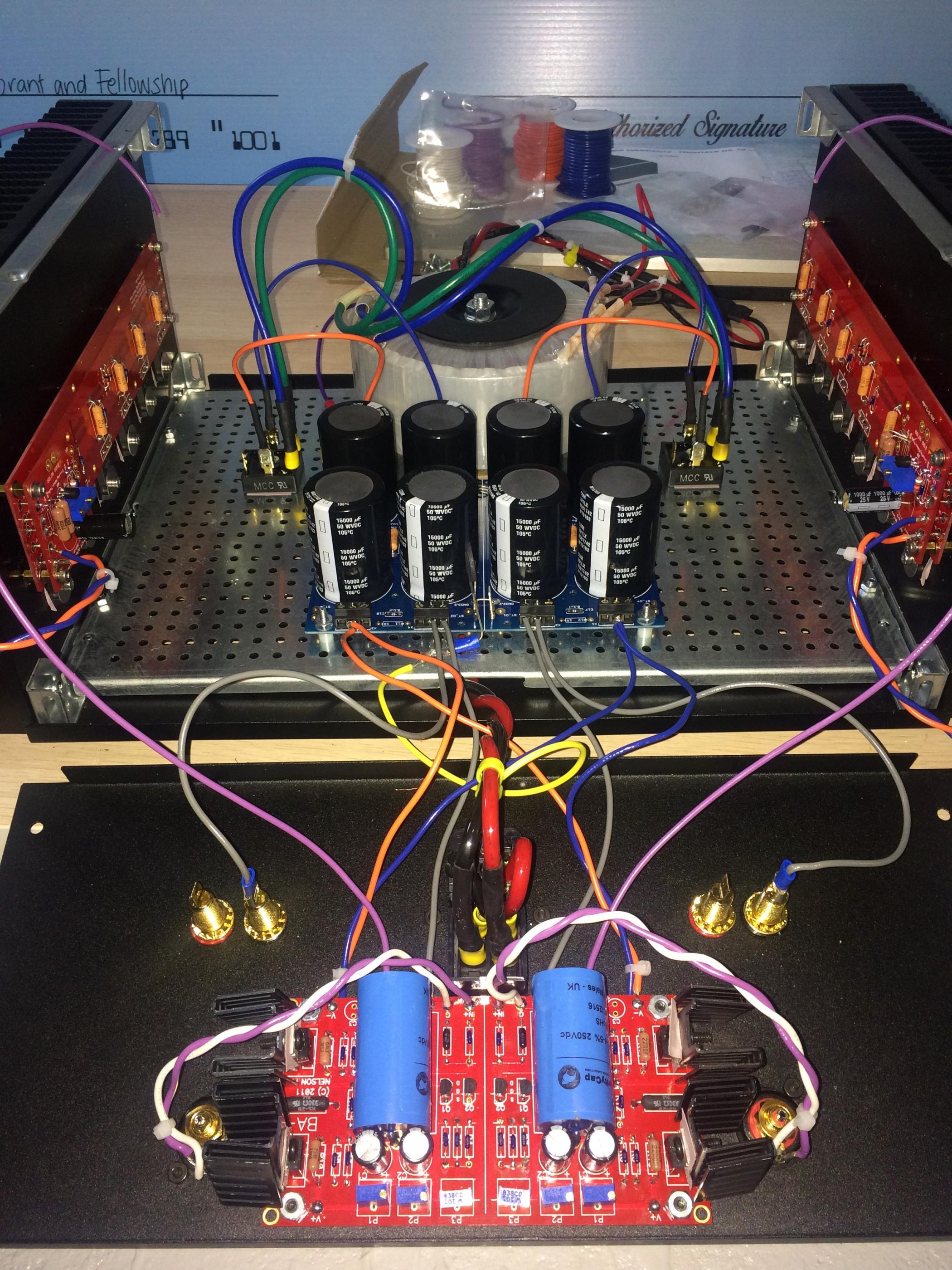
General view
FE board
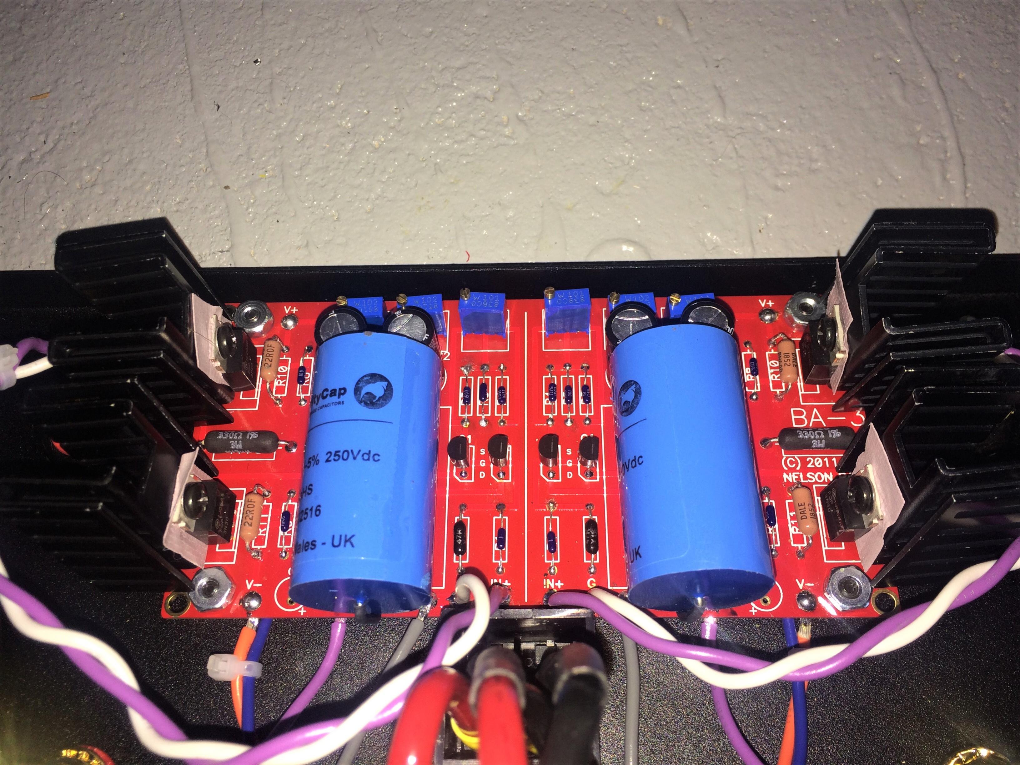

The wiring is as follows:
- Purple and White twisted: input (shorted)
- Purple: output (not connected)
- Blue: +V DC
- Orange: -V DC
- Gray: Ground
- Red: Mains live
- Black: Mains neutral
- Yellow: Mains ground
Thanks for your help! I promise it will be less messy in the end! 🙂
General view
FE board
The wiring is as follows:
- Purple and White twisted: input (shorted)
- Purple: output (not connected)
- Blue: +V DC
- Orange: -V DC
- Gray: Ground
- Red: Mains live
- Black: Mains neutral
- Yellow: Mains ground
Thanks for your help! I promise it will be less messy in the end! 🙂
Attachments

Spinin' the Ps
Cheers! Glenn
Try post 1819. I recall running into this. Neville found the solution. Page 182.Hi, everyone!
I am building my first amplifier ever, a BA-3, and all is well with the power source, the voltages (+/- 24V) are arriving at the Front-End, but when I try to bias the Front-End, nothing happens. I start turning the pots P1 and P2 and I can go until the end an no voltage happens across R10, R11 or R12. Any leads on where the problem might be? Thanks!
Cheers! Glenn
Last edited:
If you mean using 1k pots for P1 and P2, I already did that. I really don't know how to troubleshoot this, but it seems that the Q1 and Q2 network is ok, so the problem must be really in the Q3 and Q4 network.
damn good eye
When you have made a lot of mistakes it’s easy to see them. 🙂
That's when you can tell how inexperienced I am. 🙂 Thanks so much! I will post you guys about my progress.
Also, unless you are using a plastic screw and nut on those mosfet heatsinks they are not isolated from the heatsinks. If two of those heatsinks touch each other (one looks like it’s touching in the photos) it’s not going to be fun for you.
And I would make sure the wires from the ac inlet cannot touch your signal input wires from the rca jacks. I would flip the front end pcb the other way around.
And your input rca jacks are wired wrong unless you are trying to “short” them for biasing.
And I would make sure the wires from the ac inlet cannot touch your signal input wires from the rca jacks. I would flip the front end pcb the other way around.
And your input rca jacks are wired wrong unless you are trying to “short” them for biasing.
- Home
- Amplifiers
- Pass Labs
- Burning Amp BA-3