6L6 observed:
Make a Balanced BA-3 front end into a preamp. That will have enough gain to drive the F4 to clipping. Drive the F4s with that preamp. Don't cripple the F4, they sound the same wether the buffer is there or not.
I agree. With the BA-3 the replication of the 2sj74/2sk170 buffer in the F-4 works more synergistically with the BA-3. Crippled F-4 or BA-2 PP amps, I believe, may work better with x-ccs BOSOZ,such as the Pumpkin.
Collecting parts to build a balanced BA3 with comp output sections.
Is it okay to use 220R, instead of 150R, for the gate resistors at the output mosfets? I have a lot of 220R left over from previous project.
Is it okay to use 220R, instead of 150R, for the gate resistors at the output mosfets? I have a lot of 220R left over from previous project.
I would say close enough. On your next parts order include some 150R to replace but I doubt it will make any difference.
I started doing some planning to check if it's worth replacing my DCB1.
I have a question. Are there any issues with pops using the board as a preamp? Shouldn't we have a resistor shunting the output of the cap?
Oh and here is the layout I have so far. I would appreciate any input.

I have a question. Are there any issues with pops using the board as a preamp? Shouldn't we have a resistor shunting the output of the cap?
Oh and here is the layout I have so far. I would appreciate any input.
Attachments
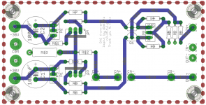
Keep in mind that at 30V your output mosfets will get hot!!! They need heatsinks, you should make space around them for that!
A resistor on the output cap is a good idea.
I'd make the layout narrower in general if you plan on floor mounting the Mosfet, the devices are TO-220 and you won't have enough room to get a tool on the mounting bolt. It looks like the device drawing is bigger than TO-220.
Is this a single-layer board?
I'd make the layout narrower in general if you plan on floor mounting the Mosfet, the devices are TO-220 and you won't have enough room to get a tool on the mounting bolt. It looks like the device drawing is bigger than TO-220.
Is this a single-layer board?
Good catch. Yes it supposed to be an IRF510 TO220, but the package design is quite bigger than the datasheet spec.
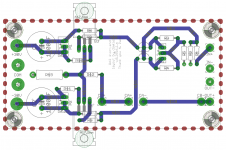
I moved the mosfets more to the sides based on the datasheet.
The contacts are now 11mm from the sides. So the entire metal part and the hole should be exposed
The PCB is double layer, but all signals are on a single layer. The other one is a ground plane.
I moved the mosfets more to the sides based on the datasheet.
The contacts are now 11mm from the sides. So the entire metal part and the hole should be exposed
The PCB is double layer, but all signals are on a single layer. The other one is a ground plane.
Last edited:
Added a few details
I added a chassis connection (keeping 0V level on the preamp pcb)
I added the output shunt resistor (R14)
I added an alternate position for R5 (R5B) with a pad (B) to allow connecting two boards for balanced operation.
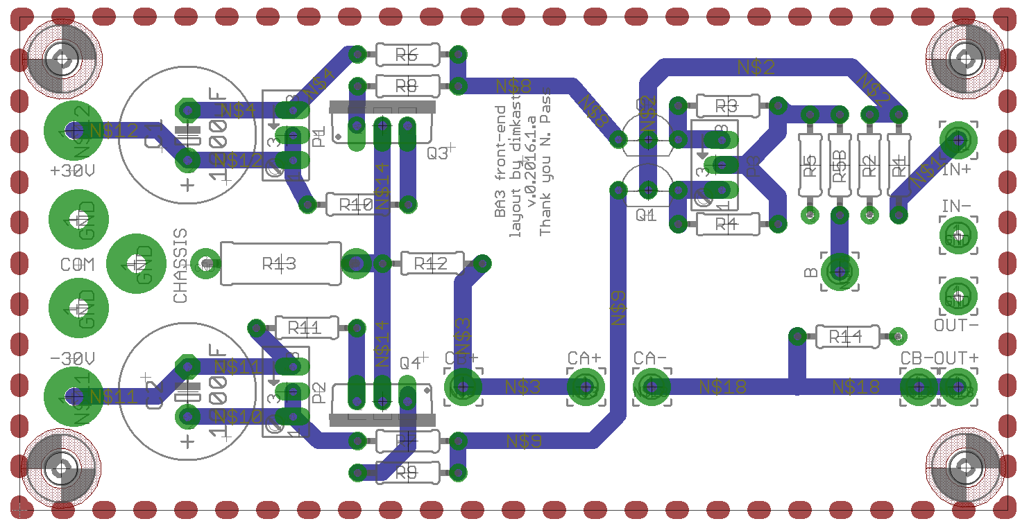
I added a chassis connection (keeping 0V level on the preamp pcb)
I added the output shunt resistor (R14)
I added an alternate position for R5 (R5B) with a pad (B) to allow connecting two boards for balanced operation.
Attachments

Last edited:
That asymmetry was killing me...
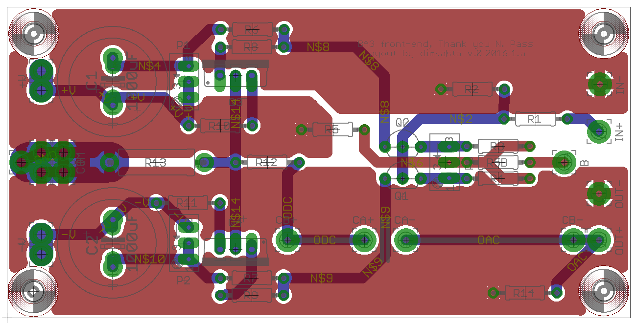
I also splitted return currents, added provisioning for sensing regs and fixed a few more minor things
Here's a preview with flooded rectangles, so that they are more obvious
The fact that the pcb can be easily split in half got me thinking...
What if keep the input separate?
Could we try different stuff? Like two outputs driven by something from the iron family to add some SUSY flavor? 🙂
Attachments

well , if by Iron Family you're insinuating .........  , then remember what I said for general approach and sane output swing
just make M2 and enjoy
, then remember what I said for general approach and sane output swing just make M2 and enjoy
Hello,
I would like to build the BA3 as preamplifier.
My question to C3, my L'Amp 193 has 10yF as input capacitor.
Can I c3 with 10yF stock or I have to take another value.
I would like to build the BA3 as preamplifier.
My question to C3, my L'Amp 193 has 10yF as input capacitor.
Can I c3 with 10yF stock or I have to take another value.
Use 10uF in the output of the BA-3. It is being used to control DC offset on the output.
The L'amp capacitor is used to ensure that no DC is on it's input, regardless of what source you use.
The L'amp capacitor is used to ensure that no DC is on it's input, regardless of what source you use.
Re reading all this is again giving me the BA3 itch. Or I should say, the BBA3. I will need to bite the bullet and by 2 more large deluxe 5 cases for the project, but I have the boards, jfets, and most of the pesky stuff already.
Rather than a BBA3 pre, I am slowly finishing a Shunty Pumpkin. It never stops...
Russellc
Rather than a BBA3 pre, I am slowly finishing a Shunty Pumpkin. It never stops...
Russellc
I would say F4 combined with a X.0 like FE, all balanced monoblocks?
I had a similar combination F4 + Pumpkin and it run marvelous!
I had a similar combination F4 + Pumpkin and it run marvelous!
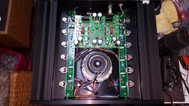
that one is something older with plenty of IRFs in preamp/FE stage
edit: now , when I blasted picture fully , I see JFet LTP , complementary ITF output , one IRF down probably for LTP CCS ...... but two 7815 and pairs of 2SK170 on sides
interesting concoction ......... though not made in a way I prefer
edit: now , when I blasted picture fully , I see JFet LTP , complementary ITF output , one IRF down probably for LTP CCS ...... but two 7815 and pairs of 2SK170 on sides
interesting concoction ......... though not made in a way I prefer
Last edited:
- Home
- Amplifiers
- Pass Labs
- Burning Amp BA-3