Major Milestone.
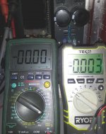
The output side is alive and behaving. The DC readings have been stable - after warm up of about 2 hours. If the power is removed and reapplied one side comes back at it's former value. The other starts with a 0.024 mV bump that falls to zero after ~ 30 seconds. Hope that goes away after extended use.
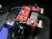
The components:
4 SE output boards - fully populated
2 Bias boards
2 500 VA - 18 transformers
2 DIY power supplies
2 Pair CL-60 - hot and neutral legs
1 2" X 3" X 11" liquid cooled heat sink with internal drain/return
1 Danger Den Pump
1 DIY water resivoir w/internal air bubble deflector.
1 10" X 6" X 1.75" automotive radiator
2 120 mm PC fans
1 4 port fan/motor speed controller
1 DIY 12 VDC modified PC PS.
116 gallons of strong coffee.😀
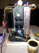
Still painfully distant from a completed formal build, but the concept appears to be valid. I hope to hook up the front later today, but want to let this cook (self basting 🙄) for a while.
The base aluminum frame is 11" W X 9" D and it's 15" from the granite plate to the top of the input caps. A detailed build pictorial will be posted on the liquid cooling thread.
As predicted by some, the heat transfer efficiency is disappointing with the Kapton tape - so far. This uses the 1 mil with most of the adhesive removed with acetone. The residual is just enough to stick to the fet and the side against the cooler has the Ceramique paste. No jumping currents, but the efficiency can be improved.
The PC power supply and the external speed controller will not be in the final build. The fans and pump will run from a single wall wart, and a new tiny internal speed controller is almost complete.
The output side is alive and behaving. The DC readings have been stable - after warm up of about 2 hours. If the power is removed and reapplied one side comes back at it's former value. The other starts with a 0.024 mV bump that falls to zero after ~ 30 seconds. Hope that goes away after extended use.
The components:
4 SE output boards - fully populated
2 Bias boards
2 500 VA - 18 transformers
2 DIY power supplies
2 Pair CL-60 - hot and neutral legs
1 2" X 3" X 11" liquid cooled heat sink with internal drain/return
1 Danger Den Pump
1 DIY water resivoir w/internal air bubble deflector.
1 10" X 6" X 1.75" automotive radiator
2 120 mm PC fans
1 4 port fan/motor speed controller
1 DIY 12 VDC modified PC PS.
116 gallons of strong coffee.😀
Still painfully distant from a completed formal build, but the concept appears to be valid. I hope to hook up the front later today, but want to let this cook (self basting 🙄) for a while.
The base aluminum frame is 11" W X 9" D and it's 15" from the granite plate to the top of the input caps. A detailed build pictorial will be posted on the liquid cooling thread.
As predicted by some, the heat transfer efficiency is disappointing with the Kapton tape - so far. This uses the 1 mil with most of the adhesive removed with acetone. The residual is just enough to stick to the fet and the side against the cooler has the Ceramique paste. No jumping currents, but the efficiency can be improved.
The PC power supply and the external speed controller will not be in the final build. The fans and pump will run from a single wall wart, and a new tiny internal speed controller is almost complete.
Attachments
-
 20130830_075739.jpg234.5 KB · Views: 559
 -
 20130830_071015.jpg693 KB · Views: 560
 -
 20130830_070958.jpg608.8 KB · Views: 537
 -
 20130830_071122.jpg557.2 KB · Views: 236
 -
 20130825_191141.jpg555.3 KB · Views: 249
 -
 20130830_071947.jpg497.2 KB · Views: 511
 -
 20130830_071033.jpg781.9 KB · Views: 511
 -
 20130830_075153.jpg143 KB · Views: 272
Last edited:
Does the "reduced" thickness of adhesive remove all air from the interface?
It's better but still takes more fiddling than other available solutions. There is more experimenting needed. I most likely will end up using the Karatherm pads.
Thanks Mr. 6. I know you will be most pleased when it's done so the emails lessen. Could not have gotten this far without your assistance and support. Your'e a gem.😉
Bob,
Very very nice! It looks like a mil grade aerospace piece of satellite hardware or maybe a high tech time machine. Cool, figuratively and actually. How many watts of dissipation is going on here and what is the audio power in watts? I don't know anything about the BA series.
Very very nice! It looks like a mil grade aerospace piece of satellite hardware or maybe a high tech time machine. Cool, figuratively and actually. How many watts of dissipation is going on here and what is the audio power in watts? I don't know anything about the BA series.
Thanks X. The cooler is based on your suggestions which were right on point. Still going to loosely stuff it with stainless Chore-Boy type material to aid heat transfer and water dispersion/circulation per your advice. The dissipation tests are still to come after the front end is on, it stabilizes and it's making music.
Last edited:
Congrats! It looks really good. As I am following you carefully on tip-toes with my own cooling tower project, it's nice to get encouragement (or is that just courage) to move forward.
Jac
Jac
Bob, have you accounted for long term water level reduction? I mean, any conventional air (wether active or passive) needs zero maintenance, but how often do you need to refill water tank, if you ever need to?
AFAIK, it has to be done from time to time... any experiment on that?
How often would I have to refill water cooling
AFAIK, it has to be done from time to time... any experiment on that?
How often would I have to refill water cooling
 🤐
🤐 🤐
🤐
ARRGGHH!!
Could you hear me screaming?? The cooler was fine. 0.0 VDC offset stable on both sides. Added front end and no sound on the left side. That was Saturday evening. Completely re-wired everything after careful inspection of all boards. Took everything apart again
 and swapped boards - still no left channel.😡
I was just about to give up and order another set of FE parts - and almost by accident found a break in a lead between the board and a resistor. The pad and the resistor were fine - the lead just split. There wasn't enough separation to see it without some physical prodding. A dab of solder and the world is good again.😀
There must be a moral to this story but I'm still too mad and worn out to think of something clever.😉 Sometimes I hate this hobby.😛
*******
Reg - My computers have not needed maintenance for periods over a year. I am however, adding a drain system that terminates at the back - external to the chassis. It will allow an active flush for both water rotation as well as dry disassembly of the amp - if needed.
Fingers crossed for STEREO tomorrow.😀
Attachments

Last edited:
I had a similar issue with a source resistor on the Aleph J - the solder joint was loose, and it was acting really, really strange. I got extremely lucky and found it, re-soldered and was good.
Hang in there!!
Hang in there!!
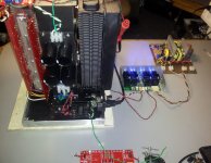
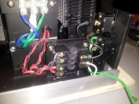
Couldn't wait till morning. See the battlefield 😉
All 24 devices running and no temp runaway -yet ~ 35 min. Have to adjust FE for balance like last time, but the sound is clean and stable.
The thermal pads are a mix of mica, silpad and the top OBs are all ceramic. Now that I know the system works I'll order the Keratherm pads from mouser. Lots more to do but the darn thing works. !!!!😀
Attachments

Last edited:
Adjustment question. Somewhere along this journey I was told to adjust for 1 volt across R11 and R12 on the BA-3 front end. Reading the Pass article again, it looks like that should be R8 and R9. Currently I have 1 V across 11/12 and 0 across 8/9. I may not even be in the ballpark. 😕
post1271,
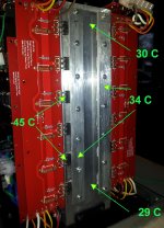
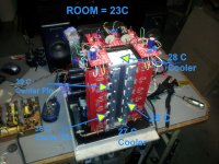
those temperatures cannot be approached with a passive cooling system.
delta Ts-a ~5C degrees.
delta Tc-s ~10C degrees.
those temperatures cannot be approached with a passive cooling system.
delta Ts-a ~5C degrees.
delta Tc-s ~10C degrees.
Andrew, 9 of the 12 pads on the bottom are mica. So the shorting I had apparently was the metallic element in the Arctic Silver paste. The Kapton tape was a bust at 1 mil. There were all kinds of currents on most of the devices - even with the Ceramique. The acetone cleaning may have broken down the insulating properties and/or the adhesive may be integral to the isolation.
I'll do a full mica install next time around. Is there a brand/formula of grease you prefer to use with it?
BTW, the mix of thermal pads was simply using what was on hand to get to a full build of the amp operational.
I'll do a full mica install next time around. Is there a brand/formula of grease you prefer to use with it?
BTW, the mix of thermal pads was simply using what was on hand to get to a full build of the amp operational.
Last edited:
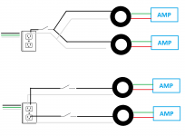
Here's one I'll run around the block again. I'm considering adding what's needed to go from dual mono to 2 mono-blocks in one chassis. The power is essentially coming from the same house feed - just joined at different spots. Does anyone have some real world experience/advice on if the sonic improvement is really worth the two extra parts (inlet & switch or inlet/inlet DPDT) in this application? The CL-60s are all isolated after the mains switch. It seems to me heavier gauge mains cables (more capacity) with the dual mono would accomplish the same goal.
I'm aware mono-blocks are considered the ultimate, but would appreciate some opinions.
I'm aware mono-blocks are considered the ultimate, but would appreciate some opinions.
Attachments
Last edited:
Changing from the top diagram on the sketch to the bottom will have no effect, other than to require more parts.
Now That's Cool!
Regarding post 1271, you have an amazing temperature margin compared to passive cooling (nod to Andrew, who has already noted this). On the the Aleph J thread, it has been suggested by Mr. Pass, Bob Ellis, 6L6, and others that this type of amp benefits from higher levels of output bias. I don't know anything about the BA-3. Is higher bias a good thing here too?
I am told that bias level is often limited by output transistor temperature. So the philosophical question, "Would Bob be better off with 36 deg C at the transistor face or with 46 deg C and higher bias?"
Deep Threads
Bob,
It looks like, in order to get the whole thermal face of the transistor on the heatsink, you have your clamping bar bolts in the part of the heatsink that is 1/4" thick. You said earlier that you didn't want holes into the water jacket. Does this mean that your threads are less than 1/4" deep?
If so, did you consider moving the transistors to the far wall of the tube so that you could thread deep into the far wall?
Any thoughts would be helpful as I am thinking about where to drill holes as we speak.
Jac
- Home
- Amplifiers
- Pass Labs
- Burning Amp BA-3