I ordered some from Farnell in the UK which appear to be the same as in Nelson's photo. I think they were 0.5W
Order code: 9355014 (100R) and 9355103 (500R).
Thank you! Those are available through Mouser but they are single turn. I was hoping for multi-turn, but because people here have used them with success, I will go with it.
Thanks all!
Get a similar multiturn of same or greater value. Greater value insures adjustability if you have jfets with lower ids. Single turns can be a pain with this circuit.
hmm.. makes sense... so, maybe a 1k instead of the 500 ohm? I think P3 should be fine at 100 ohms.
So I have the boards for a PP BA3 sitting around waiting for me to finish some other projects, but they are burning a bit of a hole and I decided to read the BA2 and BA3 threads.
Always being the one to want to push things, 25V rails just seems a bit wimpy so I'd like to bump it up, but I'm not wanting to go the cascode route.
Nelson said the following in the BA3 article
Am I just going to be producing more heat (to be got rid of by the struggling heat sinks) by running the outputs at a higher voltage than the front end? (I realise the amp is limited to the 30V [clipping wise] of the front end supply rails). Would I be better off being less of a cheapskate and get a additional traffo and rectifiers for the front end, and drop back to 21 or 22V for the main traffo's?
Another thing I've still not quite grasped is the advantage of running with 6 output pairs / channel compared to 3 pairs. I'm assuming it is for extra current delivery / ability to drive low impedance loads. My speakers are nominally 4 ohms with dips to around 2.7 ohms, so I'm not really sure if this is something I should consider or not.
If I understand it correctly I can potentially run more pairs but at lower current (per pair) and overall have the same heatsinking requirements, is there any sense in doing this though? I think I read that the mosfets perform better at higher currents, so perhaps less pairs with higher bias current is better if it can deliver the required current with the load in question?
I suspect with my 4 ohm speakers I'm not going to be able to get too many watts in class A before I drop into class B with the size heatsinks I am willing to live with. (10W should be enough anyway) Conrad Heatsinks - Products I need to derate them by a fact of at least 1.33 as 30 deg above ambient would be the max I could have in summer, which means a maximum dissipation of 107W / channel... (assuming it will be around 35 deg ambient in the lounge room at times in summer).
Sorry if this is all a bit rambling, I've got a lot going through my head with this 😉
Tony.
Always being the one to want to push things, 25V rails just seems a bit wimpy so I'd like to bump it up, but I'm not wanting to go the cascode route.
Nelson said the following in the BA3 article
So what I am thinking is that I'd like to use a 25-0-25 transformer to get around 35V rails and then run some LM317's to cut that back to 30V for the BA3 FE.The supply voltage is only critical with respect to the voltage rating of the input JFETs, which are nominally 25 volts. In actual testing, they break down around 40 volts. I wouldn't worry about running them as high as 30V. Hot-rodding this circuit would likely involve cascoding the input Jfets to allow higher voltages.
Am I just going to be producing more heat (to be got rid of by the struggling heat sinks) by running the outputs at a higher voltage than the front end? (I realise the amp is limited to the 30V [clipping wise] of the front end supply rails). Would I be better off being less of a cheapskate and get a additional traffo and rectifiers for the front end, and drop back to 21 or 22V for the main traffo's?
Another thing I've still not quite grasped is the advantage of running with 6 output pairs / channel compared to 3 pairs. I'm assuming it is for extra current delivery / ability to drive low impedance loads. My speakers are nominally 4 ohms with dips to around 2.7 ohms, so I'm not really sure if this is something I should consider or not.
If I understand it correctly I can potentially run more pairs but at lower current (per pair) and overall have the same heatsinking requirements, is there any sense in doing this though? I think I read that the mosfets perform better at higher currents, so perhaps less pairs with higher bias current is better if it can deliver the required current with the load in question?
I suspect with my 4 ohm speakers I'm not going to be able to get too many watts in class A before I drop into class B with the size heatsinks I am willing to live with. (10W should be enough anyway) Conrad Heatsinks - Products I need to derate them by a fact of at least 1.33 as 30 deg above ambient would be the max I could have in summer, which means a maximum dissipation of 107W / channel... (assuming it will be around 35 deg ambient in the lounge room at times in summer).
Sorry if this is all a bit rambling, I've got a lot going through my head with this 😉
Tony.
Always being the one to want to push things, 25V rails just seems a bit wimpy so I'd like to bump it up,
Remember that as your voltage gets bigger, your heatsinks must get bigger.
I personally do not like the single turn pots. Multi are much easier to use and adjust and will fit the board just fine. BTW. I have single turn on my boards and when i got to balanced, I will be switching them out.
Also, IMHO, the BA3 presents the kind of sound that makes me want to stop building amps. and just listen. You have before you a scalable no feedback amp that is capable of extreme low distortion and wonderful sound. I have tried IRF fets and lateral fets in output. I have yet to try Fairchild parts, but seem disinterested because they are impossible to find and i only have 6 pairs. I only have these thanks to Generg. The laterals do not push outinto the room like the IRF, but have a much richer, fuller, and more accurate tone. I have some of the fets for the EUVL f5X that i have enough of to try and may do so based on the fact they seem to work well in this type situation in my reading.
The output stage is from BA-1 or BA-2?
Remember that as your voltage gets bigger, your heatsinks must get bigger.
I guess I need to go back and find the power calcs. I also need to get out of the class AB mindset. class A constant current draw, so therefore higher voltage means higher watts dissipated at Idle... So I guess that really answers my question.
Having output rails higher than FE rails is basically just wasting power correct? If I need 5V higher for my reg (for maximum effectiveness), then I should look at implementing a separate transformer for the regulated FE.
edit: So basically if I have 30V on the FE, there is not point having any more than 30V on the output, it will just waste power correct?
Tony.
Last edited:
Having output rails higher than FE rails is basically just wasting power correct? If I need 5V higher for my reg (for maximum effectiveness), then I should look at implementing a separate transformer for the regulated FE.
edit: So basically if I have 30V on the FE, there is not point having any more than 30V on the output, it will just waste power correct?
Tony.
I think so. There are many builders who just happen to have a transformer lying around which they want to use and will run an amp at a higher voltage as a result. Good resource management.😀
From experience I would try the Nelson's power supply first because if you choose good components it produces a very good sound indeed even without a regulator. I really think it is a useful benchmark. The wrong regulation will undermine the sound and in tests I've made with the LM317 I have often preferred a good quality C-R-C circuit. The Salas reg which I am using with the BA-2 font end can be excellent--have a look for my posts on this--but it is much bigger in size, and yes I do use a separate power supply for this.
Chris
Last edited:
As a matter of interest, how many of us are using some form of regulator for any of the BA-2, BA-3 front ends?
Who is keeping up on the F5 turbo thread (diodes across resistor debate)same result ...more voltage swing.
Regards, E
Regards, E
Diodes are interesting when low impedance loads are used as they increase considerably the available current. Though, in that case, it's not the voltage that counts.
Using 8 ohm load, little voltage is gained as long as voltage drop across source resistors is not that high.
Using 8 ohm load, little voltage is gained as long as voltage drop across source resistors is not that high.
I have a BA-2 and was thinking of trying the BA-3. I have separated the PCBs for left and right FE for my BA-2 and I would like to do the same for BA-3 to be able mount them in the same place using the same wiring. When I checked the pictures of the BA-3 boards in the diyaudio shop I noticed that they do not have mounting holes in the middle. So if I separate the left and right FE I will only have mounting holes in one end of them. Is this done by purpose? Is there a reason why one should not separate left and right PCBs?
Attachments
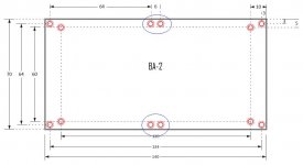
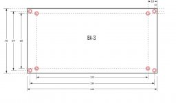
It just got too difficult for Papa to fit everything in and we didn't think many people were cutting them.. .. As far as I know, there is no reason not to cut them. Using 2 holes on the side of each piece is probably enough. and there's a line to help guide your Dremal tool!
Which of the corner holes are you using? the ones in the extreme corners or the ones inboard a bit?
Which of the corner holes are you using? the ones in the extreme corners or the ones inboard a bit?
Thank you for the quick answer Variac. I am using the holes in the extreme corners but maybe I should use the other holes for the BA-3 to get a little better force distribution?
I think either way will be fine, but I guess the inner holes would be stronger.
But bolting them right in is pretty appealing, right?
But bolting them right in is pretty appealing, right?
The output stage of BA1 works in pure single-ended.
With 0.58 A per MOSFET (6), the BA1 provides, with ± 32V, 50 watts into 8 ohms, 25 watts into 4 ohms but only 12 of 2 ohms, ...
Is there a "small" circuit that could push the output stage in class AB (in the style of the Aleph 0, 0s and 1), for at least 50 watts into 4 ohms and 2.
Regards
Darry
With 0.58 A per MOSFET (6), the BA1 provides, with ± 32V, 50 watts into 8 ohms, 25 watts into 4 ohms but only 12 of 2 ohms, ...
Is there a "small" circuit that could push the output stage in class AB (in the style of the Aleph 0, 0s and 1), for at least 50 watts into 4 ohms and 2.
Regards
Darry
- Home
- Amplifiers
- Pass Labs
- Burning Amp BA-3