I'm just playing with amplifiers as my F5 build was sadly very disappointing.
I've bought a few of these Chinese Burmeister 933 Mk2 Clone kits and have a few questions.
Ebay item 271524655114
Some of the components supplied were different from the values on the PCB. OK I accept that he has supplied some E48 values in place of E24 parts, I have no problem that 216R is close enough to 220R.
However he has supplied 0R27 emitter resistors, the board shows 0R47. Is this an issue or should I obtain the 0R47 parts ?
I ordered the output transistors from the item photo, 2SC3264 and 2SA1295. The PCB shows 2SA1216 and 2SC29??. Will this be an issue ?
The advert states 120W into 4 Ohms. What can I expect into 8 Ohms. I am using the rails as suggested in the advert. I'll be using a 40-0-40VAC 800VA transformer.
Last edited:
Nice kit.
Your 2sa/c Sankens will be a perfect match for the older (other ones).
.47R to .27R will slightly change the settling time - thermally , your
current/bias calculations will be different if the documentation is
calculating for the .47's.
With those sankens , 120w/4R - 70w/8R is a "honest" spec.
An 800VA trafo is total overkill. (no harm )
I use 600-800VA units for 2 X 300W "monster amps" 😀.
good luck ,
OS
Having difficulty uploading
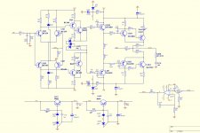
I did try to upload the schematics for the Clone yesterday but Internet Explorer was having none of it. I did uninstall Google Chrome because that wasn't working either. I've just re-installed Google Chrome and can now upload the schematics for anyone who wants to comment.
Vendor states that 22K and 27K are interchangeable with no consequences.
He also states that 0R27 is fine in place of 0R47. I've got the correct components so I'm going to stick with the schematics, the only difference is the more modern output transistors.
Attachments
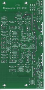
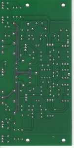
The PCBs are of a good weight and are well made.
Any comments about the layout or design ?
Building these is fairly intuitive, just as well as there are absolutely no instructions.
There are two test points marked TEST. You have to reverse engineer the board to discover that they are across the upper emitter resistor.
The bias current is 200mA but with the wrong resistors supplied.
Some of the transistors are second hand but for the price I've got no qualms with that, at least they are probably genuine.
Attachments
Studying the schematic against the component count there are a few questions.
I'm presuming that LD5 and LD6 are the two CCS semis fitted.
LZ1, LZ2, LD7 - 10 are the zeners fitted.
How has the vendor got rid of the diodes between LQ6 and LQ7, there are no other diodes on the board.
I'm presuming that LD5 and LD6 are the two CCS semis fitted.
LZ1, LZ2, LD7 - 10 are the zeners fitted.
How has the vendor got rid of the diodes between LQ6 and LQ7, there are no other diodes on the board.
Hi,pm your email address.I have a bom and schematic for a clone from another supplier that seems to have all the diodes that you are looking for
😕😕😕Vendor states that 22K and 27K are interchangeable with no consequences.
If that would be true, why put effort in designing an amplifier...

Output voltage vs supply rail.
Hi, i also have this amp.
My supply voltage is +/- 40v but the output signal is already distorted at +/- 30V. This means you loose 10V on each side of the supply rail. Does someone have any idea why it is this high? Some volts is ok, but this is to much.
I had to place a 22pf parallel on R25 (27k) according to the circuit in this tread.
otherwise i had some ringing when a square wave form is connected to the input.
They are selling these fully built for $50 to $60 a pair - how do these amps sound? Are they worth $60?
Online Shop One pair Assembled amplifier board base on Voice of Berlin 933 lines amplifier board|Aliexpress Mobile
Online Shop One pair Assembled amplifier board base on Voice of Berlin 933 lines amplifier board|Aliexpress Mobile
Yes they measure good. I did not really listen carefully yet.
How much voltage are you running them with and how much gain do they have? Will I need a preamp or will typical RCA line levels from a miniDSP be able to drive it ?
Burmester 933 MK2 Clone (Amp board only) - problem
Hi Folks,
I built a Mono Block Amp using the ebay Burmester 933 MK2 kit (Amp only) with +/-50VDC (300VA torodial) and a Speaker Protection board also from ebay (utilizing 2 Omron relays).
Problem I encountered: the 4.7ohm (0.5 watt) resistor is smoking when connecting a preamplifier (EAD Ovation); When only the speaker is connected (8 ohms) the resistor is not smoking; the Speaker Relays activates ~6 seconds after powering up the Amp. The input resistance of the Amp is ~24k while the output resistance is ~6k.
Can anyone help please.
Thanks,
Shalom
Sounds like you have oscillation when connecting the preamp as the 4.7R 0.5W is the Zoble connected through the capacitor to ground. Since the oscillation is not there without the preamp, it's probably introducing some higher frequencies that are not getting suppressed. You need an oscilloscope and maybe try increasing compensation cap values while observing oscillation.
As a test to see if it helps, try changing LR1 to 100R and LC0 to 670pF to suppress input RF even more.
As a test to see if it helps, try changing LR1 to 100R and LC0 to 670pF to suppress input RF even more.
Last edited:
It's a miserable design if I may say so.
No protection against output overload.
The VAS supply is "stabilised" but drops together with Vcc at supply voltages lower then 49volts.
With 60volts supply the output swing gets no further then 42volts (with 0.47 not even 40V).
Those LD5/6 CCS are far from exact, you have to select a pair to get the amp balanced.
If the amp has to be used at high power you need big cooling,more then 50% of the output power goes up in heat.
Mona
It's a miserable design if I may say so.
I wonder if the real Burmester 933 has the same circuit? They are really well-regarded amps in commercial world.
Sounds like you have oscillation when connecting the preamp as the 4.7R 0.5W is the Zoble connected through the capacitor to ground. Since the oscillation is not there without the preamp, it's probably introducing some higher frequencies that are not getting suppressed. You need an oscilloscope and maybe try increasing compensation cap values while observing oscillation.
As a test to see if it helps, try changing LR1 to 100R and LC0 to 670pF to suppress input RF even more.
THANK YOU SO MUCH FOR THE FEEDBACK; WILL TEST AND WILL UPDATE; SHALOM
you may need to double up the outputs if your speakers are less then 4 ohms.
40-0-40 VAC = 55 volt rails. The power dissapation in the outputs will be 190w /2 = 95 watts each.
40-0-40 VAC = 55 volt rails. The power dissapation in the outputs will be 190w /2 = 95 watts each.
- Home
- Amplifiers
- Solid State
- Burmeister 933 Mk2 Clone