carlosfm said:
Yes.
The problem is the two 0V wires.
In fact, it works MUCH BETTER if you join the grounds of the two channels with a very short (but thick) wire and then run a single thick wire from a midpoint of that short wire to the 0V point on the PSU.
No more noise, just complete silence.
This is new to me.
How come this circuit recommends seperate 0V wires until star ground? What's the idea behind it?
I did as on the circuit and does not have any noise.
http://ampchipdiy.com/invertedLM3875_r2_1.gif
/Jan
2Bak said:
This is new to me.
How come this circuit recommends seperate 0V wires until star ground? What's the idea behind it?
I did as on the circuit and does not have any noise.
http://ampchipdiy.com/invertedLM3875_r2_1.gif
/Jan
That schematic is for one channel.

For two channels you should have two transformers.
With only one trafo, just do as I say, it's better.
Put your ear on the speaker and take the volume to the max.
You'll hear some noise.
If you make as I said, you won't.

2Bak said:
This is new to me.
How come this circuit recommends seperate 0V wires until star ground? What's the idea behind it?
I did as on the circuit and does not have any noise.
http://ampchipdiy.com/invertedLM3875_r2_1.gif
/Jan
By doing that you are crating shorter GND loop, so less noise. Don't forget that the GND of the L and R chanels are connected together at the source. As Carlos mentioned it's valid only for 1 transformer for the two chanels setup. With 2 separate transformers (secondary windings) it doesn't matter.
2Bak said:OK
I understand.
I have two 250 VA trafos with single 26,4 v secondaries. Do they count as one trafo then?
In the sch you have, the two trafos are connected as one trafo configuration. Only if you have separate GND for L and R canel. In your case it's the same GND point for both chanels. If you had two trafos with 2 secondary windings each, than it doesn't matter.
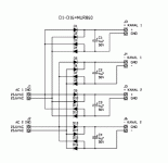
2Bak said:schematics
Hold on. I'm confused now with this one. I have to think. Sorry.
I'm not 100% sure, but because the separate bridges it might not be as sensitive to the GND connection, but I'd still do what Carlos suggested, just in case. Do it both ways and tell us if there is a difference.
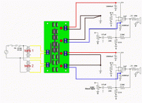
One transformer two channels
... ok, so where the ground point is ? Is it at the bridge or at this short thick kable ? I mean where is the place where the two polarities (+) and (-) are joined ? Is it on the bridge, i.e. only one cable connect the ground to this "center single thick wire", or is there two cables from the bridge and they are connected right at this "center single thick wire" to form GND ? ... or doesn't matter ?
carlosfm said:
Yes.
The problem is the two 0V wires.
In fact, it works MUCH BETTER if you join the grounds of the two channels with a very short (but thick) wire and then run a single thick wire from a midpoint of that short wire to the 0V point on the PSU.
No more noise, just complete silence.
Get on with it.
... ok, so where the ground point is ? Is it at the bridge or at this short thick kable ? I mean where is the place where the two polarities (+) and (-) are joined ? Is it on the bridge, i.e. only one cable connect the ground to this "center single thick wire", or is there two cables from the bridge and they are connected right at this "center single thick wire" to form GND ? ... or doesn't matter ?
Re: One transformer two channels
In my case I have the two bridges next to eachaother and the + and - of the bridges ar connected wit a 1cm long bare wire. That's the PS Star-GND in my case. From that point you can run a single wire to the amp. and to chassies thrugh a RC network.
vladimir said:
... ok, so where the ground point is ? Is it at the bridge or at this short thick kable ? I mean where is the place where the two polarities (+) and (-) are joined ? Is it on the bridge, i.e. only one cable connect the ground to this "center single thick wire", or is there two cables from the bridge and they are connected right at this "center single thick wire" to form GND ? ... or doesn't matter ?
In my case I have the two bridges next to eachaother and the + and - of the bridges ar connected wit a 1cm long bare wire. That's the PS Star-GND in my case. From that point you can run a single wire to the amp. and to chassies thrugh a RC network.
Re: Re: One transformer two channels
Thanks for your reply. Are speaker terminals (-) connected to your Star-GND or at the place where two 1000uF caps are joined (near the chip) ? And how your signal/low power GND is connected to this star-gnd ?
In my current GC I have one transformer, only one bridge (tried one, two and four, but one sounds the best for me, sorry 🙂 ), two secondary windings are joined on 1000uF caps near the chip - my power GND. Second channel is connected in parallel to the first at the bridge for (+) and (-) and at the transformer (gnd). So I have 2 (L/R) x 4(+, sec A, sec B, -) x ~ 1 m of cable from PSU to GC. Left and right power GNDs are not interconnected (only at the transformer). I have no hum but a bit of low level noise (audible at 5 cm from the tweeter - I'm triyg to solve this noise).
GregGC said:
In my case I have the two bridges next to eachaother and the + and - of the bridges ar connected wit a 1cm long bare wire. That's the PS Star-GND in my case. From that point you can run a single wire to the amp. and to chassies thrugh a RC network.
Thanks for your reply. Are speaker terminals (-) connected to your Star-GND or at the place where two 1000uF caps are joined (near the chip) ? And how your signal/low power GND is connected to this star-gnd ?
In my current GC I have one transformer, only one bridge (tried one, two and four, but one sounds the best for me, sorry 🙂 ), two secondary windings are joined on 1000uF caps near the chip - my power GND. Second channel is connected in parallel to the first at the bridge for (+) and (-) and at the transformer (gnd). So I have 2 (L/R) x 4(+, sec A, sec B, -) x ~ 1 m of cable from PSU to GC. Left and right power GNDs are not interconnected (only at the transformer). I have no hum but a bit of low level noise (audible at 5 cm from the tweeter - I'm triyg to solve this noise).
- Status
- Not open for further replies.
- Home
- Amplifiers
- Chip Amps
- Built my Gainclone today!

