It was a rainy day, the game was off because of it, I had the samples LM3875 so I caved in and built it.
I put together my 7-component GC today using what I think is Peter's schematics. Since I had a trasfomer with 2 CT secondaries I did a dual mono. The rectifiers are standard monolithic bridges digikey stuff. For PS I used 20 Panasonic FC 2200/50V/chn. The input cap is the N-type BG 4.7/50V
the resistors are NOS corning rn60 (or whatever they are called).
Quick listening test:
They are driving my MTM speakers (not the ideal load), the sound is "snappy" and transparent, imaging is better than the AX probably because of the dual mono PS. Nice mids maybe not as round as the AX. Overall it gives me the impression of being a little "Hi-Fi" sounding, as they say. Bass is a problem, sloppy and weak like the amp is running out of juice big time. I have no doubt it is, on these speakers. I may replace the rectifiers but they are the same type as on the AX. Only a deaf person would have a problem telling these two amps apart, they are indeed very different. I am ready to take my $10,000 blind listening challenge. 😉
I had listened to the GC before on a pair of small speakers it fared better in the bass dept probably because the speaker didn't have bass to begin with.
Only a deaf person would have a problem telling these two amps apart
Judging by some current discussions you've come to the right place 🙂
Are you really using 20 PS caps?
Your observations seem spot on - the GC doesn't like heavy loads.
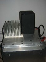
The Gainclone is "now playing" it's really heavy pics will come later. It is built like a monster and it looks like a monster, since I use the chassis of the Hiraga Monstre. It is a tube-like chassis open at the bottom made with 2x1/4 in channel, 1/4 in plate and 1/2 inch main plate, all recyled Al.
Why should anyone doubt that I used 20 caps/chn to keep the ESR low?
Anyway, although the sound is pretty good it's not at par with the AX, especially under the point of view of load versatility. It was very much a learning experience though! Now I know that the AX is NOT yet optimal, and that there is more to be squeezed out of the design in terms of imaging and transparency where the gainclone seemed to excel.
Incidentally, I am using BG for input caps of both amps. When I put them into service in the AX they permanently ruined the sound taking the magic out of the mid-high, I think they are probably not doing any good in the GC.
I think I will have to take the hit with some Auricaps or Dynamic caps.
It is built like a monster and it looks like a monster
A statement like that and no photos yet. Inquiring minds need to know.
I have built many IGCs,they perform best with =>86db/watt/meter and 8ohm drivers with either MLTLs or horns.
ron
ron
Hi Grataku...
I don't understand this line:
===I am using BG for input caps of both amps. When I put them into service in the AX they permanently ruined the sound taking the magic out of the mid-high, I think they are probably not doing any good in the GC.===
Is it mean that AX doesn't sound good with BG ??? 😕
Regards Josip
Ok, since I am home for a couple more hours...
it's just sitting on top of the AX.
Joke,
the AX is still "the more solid all around performer" IMO even with the BG at the input. However it is much better without them.
I would keep the GC online if it wasn't for the bass and the little anemic midrange that can be heard especially when playing jazz. I don't mind having experienced the GC first hand it has given me a lot to thing about and to do. I see alot of potential for the LM3875 in active sytems.
Attachments
My Gainclone dramaticlly improved in bass performance after changing regular rectifire gridge for MUR860 ones from ON-Semi.
Being much weaker than bass from my Aleph 3 ,before ,now is even a little better.I'm using copper foil /paper in oil input capacitors and 1000uF Panasonic FC directly on the chip.
Bartek
Being much weaker than bass from my Aleph 3 ,before ,now is even a little better.I'm using copper foil /paper in oil input capacitors and 1000uF Panasonic FC directly on the chip.
Bartek
grataku said:Ok, since I am home for a couple more hours...
it's just sitting on top of the AX.
That's one heck of an amp.

It's build like a tank, and i like it !
I just hope it sounds better, than a tank.

Grataku,
Sorry that does not qualify as a gain clone. It is too big. 😉
See Peter Daniel for size constraints and a copy of the regulations......😀
Regards,
Jam
Sorry that does not qualify as a gain clone. It is too big. 😉
See Peter Daniel for size constraints and a copy of the regulations......😀
Regards,
Jam
Size doesn't matter (when you have a big GC)
The transformer is a potted RCA that was probaby used for biasing tubes it's only 350VA but it's nice because of the two secondaries.
I used the chassis to try out a variety of designs, it's good enough to test out a stereo 30w classA amp and I can heat up the water for the tea
One day I will change the diodes, I have a few fast diodes I may try. I need to print out a few rectifier boards. I hope to be surprised. 😉
The alephX is now back online, this little chip-amp diversion has a renewed my faith in PassLabs designs!
Why don't you disconnect all the other 19 caps and use the single ones directly at the pins and then comment on the difference in this thread 😉 http://www.diyaudio.com/forums/showthread.php?s=&threadid=21256&perpage=15&pagenumber=1
Doing this, changing for different diodes and using not CT secondaries will improve your GC. Also you don't need coupling BG if your source doesn't produce offset. I once also disconnected Aleph X and tried GC. It is still online😉
Doing this, changing for different diodes and using not CT secondaries will improve your GC. Also you don't need coupling BG if your source doesn't produce offset. I once also disconnected Aleph X and tried GC. It is still online😉
Help on Power supply
Dear all
I’m considering building a clone and although not my first project I am a relative beginner in this area. I have the circuit and sourced the parts but I need some advice on the power supply. Easy if you use one transformer per channel but to start with I want to use one transformer for both.
Confusion comes in how to connect up both channels to one transformer. Can any one help? With 4 wires from the secondary and say a 2 X 25V secondary supply when you connect them will you get a 50V out put from the rectifier or +25V, 0, -25V rails? If so how do you connect up the two channels from there? Can you parallel them? Will this have an effect on what VA rating you chose? What is a good supply voltage from a transformer?
Sorry if I sound ignorant its just that I am!!
Thanks
Matt
Imagine building supply for just one channel, and then run another set of parallel wires to the other channel (so all your wires double, 8 altogether).
Check Nuuk's site for more details http://www.decdun.fsnet.co.uk/gainclone.html#top1
This is probably most extensive GC info on the net😉
Check Nuuk's site for more details http://www.decdun.fsnet.co.uk/gainclone.html#top1
This is probably most extensive GC info on the net😉
Hi Matt,
Build your PSU, so that you have three wires coming from the rectifier (or after the 120uF caps if you are using them as I did). Then connect both amps to those thee points, ie two wires each for positive rail, negative rail and 0v rail.
I found this arrangement to work OK with one exception when I got some motorboating with some full-range speakers.
Welcome to our growing South West GC builders 'club'.
Nuuk said:Hi Matt,
Build your PSU, so that you have three wires coming from the rectifier (or after the 120uF caps if you are using them as I did). Then connect both amps to those thee points, ie two wires each for positive rail, negative rail and 0v rail.
I found this arrangement to work OK with one exception when I got some motorboating with some full-range speakers.
Yes.
The problem is the two 0V wires.
In fact, it works MUCH BETTER if you join the grounds of the two channels with a very short (but thick) wire and then run a single thick wire from a midpoint of that short wire to the 0V point on the PSU.
No more noise, just complete silence.
Get on with it.

Thanks. So easy when you know how!!! I'll try to figure this out. I did think the supply would be the easier part but it does get a bit confusing as people seem to use different voltages and cofigurations.
Thanks to every one who replied.
I'll get on with!
Thanks to every one who replied.
I'll get on with!
Nuuk - Hi
I'm from Sommerset too. - Small world - small amp!
Your site is very very good and a great help.
And I think I need it! going to order the parts for a non inverting clone as a first off.
Regards to all
I'm from Sommerset too. - Small world - small amp!
Your site is very very good and a great help.
And I think I need it! going to order the parts for a non inverting clone as a first off.
Regards to all
I'm from Sommerset too. - Small world - small amp!
Hi Matt, you in advertising? if we were selling these amps that would be one hell of a slogan 'Small world - small amp'!
So that's (at least) three GC builders in Somerset now!
Good luck with yours, if you need help feel free to contact me direct (you can use the form on DD).
- Status
- Not open for further replies.
- Home
- Amplifiers
- Chip Amps
- Built my Gainclone today!