Help! I had a perfectly working DAM 1121 until I recently moved. The output now sounds as though its over driven, raspy sounding. Checked all the input voltage levels, they all looked correct.
FYI - I use 3 Salas BiB shunt regulators for the digital 5V, analog +/- 5V.
Any clue on where to troubleshoot?
FYI - I use 3 Salas BiB shunt regulators for the digital 5V, analog +/- 5V.
Any clue on where to troubleshoot?
Last edited:

I'm askin for the 0,02% version with Si514 - the Si570 don't seem to have the same pinout... well for power they seem equal..
//
//
Last edited:
Sören, is there room for an improvement beyond size and cost limitations for the 1121 in the power supply of the clock? Please advice if so...
//
//
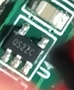
Well, its safe to say that it is a regulator I think - but which?
Maybe. Could also be something like: https://www.torexsemi.com/file/xc61...XC6112-XC6113-XC6114-XC6115-XC6116-XC6117.pdf ...Measuring voltages should make it more clear.
Last edited:
Hi!
Has anybody done any improvements to the powering of the clock on 1121? How? Pictures?
//
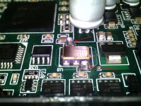
Here's what I did on the DAM1021,
I've added caps to the two nearest caps of the clock, to get best decoupling into MHz.
If there are vias around those two caps in the 1121, the same should be possible
Are you sure that "bigger" elytics do the best decoupling "into Mhz"? I thought one used small values with low resistance at RF - this means I suppose low inductance which in turn requires short distances / physically small caps - no?
//
//
No, that's the duty of the extra ceramic caps I've installed: 10nf C0G, 100pf C0G, 47uf X5R
on top of the existing 4.7uf X5R
on top of the existing 4.7uf X5R
Aha - you mean other than the big polymer that you showed photo of - sorry, I didn't get that!
It looks like this in post #903 above.
//
It looks like this in post #903 above.
//
Last edited:

No - you did B, didn't you?
And there not the same reg as in 1021. And there seem to be a filter here which is not in the 1021... so improved in 1121... maybe not much to gain here.
I'm hesitating.... 🙂 for 1021....
//
And there not the same reg as in 1021. And there seem to be a filter here which is not in the 1021... so improved in 1121... maybe not much to gain here.
I'm hesitating.... 🙂 for 1021....
//
Last edited:
I did a bit more than A or B 🙂
I've removed also the 4 ldo and replaced them with muzgdiy v3.1 regs,
see pics in DAM thread
I've removed also the 4 ldo and replaced them with muzgdiy v3.1 regs,
see pics in DAM thread
Yes I saw that - a little over my surgical level 🙂 I have found the boards to be sensitive for vibration - its quite clear as you start to play loud. For this reson one don't want bigger components swaying above the board picking up vibrations - maybe you should try some stays and see what happens 🙂
//
//
A good 60fps HDMI microscope with a 0.5x Barlow lens helps a lot for your surgical skills 🙂
Yes, when I plan to put my board in a case the board will be on rubber spacers,
maybe this year 😀
Yes, when I plan to put my board in a case the board will be on rubber spacers,
maybe this year 😀
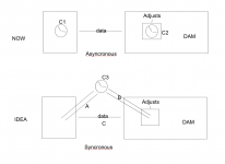
Anyone tried feeding I2S_LRCK_O and I2S_BCLK_O into a Raspberry Pi source? So that the RPi uses the dam's clock to generate I2S data instead of its internal clock?
I tried on my single-board dam1121-01 but to no avail. I'm not even sure it could... is the dam's clock running at a set frequency at all, or does it first wait for an external I2S clock signal to match?
What I did was tap J3 pins 9 and 11 (before the 3K3 strapping resistors to ground -- as per the example schematic) and feed them to GPIO 35 and 12 on the isolated header of an IanCanada IsolatorPiII board. This resulted in no audio regardless if the IsolatorPiII was in master or slave mode.
I'm not sure it'd matter much, but thought it wouldn't hurt to try!
- Home
- Source & Line
- Digital Line Level
- Building with the Soekris dam1121