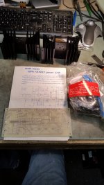
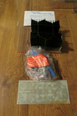
Cruising eBay the other day I came across this interesting 120 watt Mosfet Amplifier kit. I placed my bid for a few bucks and won it! the 4 NOS Hitachi mosfets alone are worth several times what i won it for. Sadly there was only one and I seriously doubt i will find another so I thought it would be fun to build this as a General Purpose Shop duty amplifier.
I didn't know anything about these kits. but apparently this was from the Mark V era of kits? and I found a thread here on DIY that appears to be related.
https://www.diyaudio.com/forums/solid-state/134481-eti-477-resurrected.html
there are several mods mentioned in this thread and I thought a review of them and any others to help make this a solid reliable amplifier might be in order. your input is welcomed.
Zc
Attachments

I'm shocked...131 views and not a single comment good or bad? that's weird! LOL! usually you guys are full of beans with comments pos and neg!
The ETI 5000 was a later more elaborate design.
Kitsets for the ETI 477 date from the 1980's and were being sold through outlets like Dick Smith Electronics and eventually became available on offer at a bargain price.
A friend of mine snapped up two and built a stereo pair and we auditioned this system in comparison to some other DIY amplifiers through his Cerwin Vega speakers - a large high sensitivity three way type with piezo tweeters.
His music preferences were different to mine so there are too many variables to be able to give an informed comment about the sound.
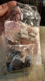
i had time tonight to assemble most of my board. the input transistors and constant current are MPSL01's but all the others are TIP31/32's which I am betting could/should be replaced with better devices.
Sound quality is not really my main concern with this kit. I will use this for general purpose shop duty. testing speakers, driving speaker test cabs. possible driving AC motors for speed control etc etc. just general shop duty and not audiophile grade anything.
Sound quality is not really my main concern with this kit. I will use this for general purpose shop duty. testing speakers, driving speaker test cabs. possible driving AC motors for speed control etc etc. just general shop duty and not audiophile grade anything.
The best of these designs was the ETI6000, from Prof David Tillbrook. Quite complex, dual differentials, but good sounding and reliable. The ETI was not a good sounding amp, I built one and found it very ordinary.
HD
HD
i had time tonight to assemble most of my board. the input transistors and constant current are MPSL01's but all the others are TIP31/32's which I am betting could/should be replaced with better devices.
Sound quality is not really my main concern with this kit. I will use this for general purpose shop duty. testing speakers, driving speaker test cabs. possible driving AC motors for speed control etc etc. just general shop duty and not audiophile grade anything.
I have a derivative of the ETI477 in an edition of collected project from ETI, which includes ETI499 a "General Purpose 150W power amp module".
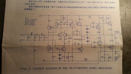
If you compare this to the schematic you have, there are some changes to resistor values, transistor types, and the compensation method. The 12pF lead capacitor in parallel with 22k has been replaced by R12 in series with C4.
The MOSFET stoppers are 220R with gate to source capacitors of 330p for the 2SK134. The top ends of source resistors R22 and R24 are co-joined by C7 under the pcb.
The BF video transistors were the best alternatives to the Hitachi devices designed for their MOSFET applications - then available from sources in Australia.
These are a bit rare now although Jaycar Electronics still have them in their latest catalogue. There may be other alternatives to the Hitachi devices.
In the commentary it is claimed the design is based on the Hitachi application - in that regard the 12 pF lead compensation capacitor is a departure from the original script.
Attachments
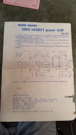
The ETI KIT is really based on an application note from Hitachi. Around 1980, a 150W MosFet power amplifier is presented in an Australian DIY booklet. Author was David Till Brook.
Here in Germany, the complete construction report was published in the magazine ELRAD, as well as the associated preliminary stage.
Here are already the modifications the user Mjona has described. Should be taken over necessarily because this suppresses a tendency to vibrate the amplifier. This construction report was my start in the home improvement scene and I still own the power amp and the pre-amp. Both are fully functional and are very well done in my eyes. Are still in use today. Sure, there will be even better amps here, but the foundation is good. Here you can learn a lot and there is a lot of room for improvement. (Input stage, driver stage, power supply). Some of it has meanwhile flowed into my power amp.
Not quite. Here's a short history and actual ETI477 schematic which is a little more complex than Hitachi's minimal power application note design, as we might expect from a mathematician such as the designer, David Tilbrook. Fixing the ETI 477 100W Audio Amp module – Blogubarra
By contrast, Hitachi's app. note became entrenched in the UK sound industry and DIY without much further development. It still turns up regularly as the basis of many Latfet designs posted here.
The ETI477 boards were marketed as part of a complete kit amplifier with the title ETI 5000 - the precursor to AEM 6000 (see the thread on a modern reworking of that by SuzyJ). ETI 5000 MOSFET Power amp. This was also a complete amplifier design and a lot more than just a single power module. I still have my 5000 build from 1982, lying somewhere at the bottom of a stack of amps in my shed. It featured 2 pairs of TO3 Latfets, beryllium thermal washers, a custom cast, full rack width heat sink and twin power supplies etc. It was quite an expensive kit for the time and the matching preamp was really something else again.
Last edited:
Very interesting. SO. In the interest of reliability. again, My intent is to use this as a GP shop amp and not a audiophile home amp, my intent is stability and reliability. what mods should be done to make it as stable as possible??
I read the article/Vlog above and will make sure the caps are away from heat sources etc.
I read the article/Vlog above and will make sure the caps are away from heat sources etc.
There were are a lot of GP amps that are just the app. note design, a power supply and little more, apart from I/O connectors. They are still very reliable in any Mosfet package form, due to the inherent current limiting - not subject to thermal runaway.
An obstacle now though, is locating fast enough drivers, since BF469/470 CRT video drivers and Hitachi's specified types were obsolete long ago. They need to sink quite a bit of heat so replacements that are also video drivers, such as 2SC3503/2SA1381 that are well known here, are some of the few remaining thru-hole options. There are SMD options but that's another issue.
Don't skimp on heatsinking for the drivers if you need reliability.
You might want to check some of nigelwright7557's threads for details of Maplin's GP Mosfet amplifiers. I'm sure he's reworked the basic design as adapted by Maplin in the UK and sold there in various size versions as a kit of parts, over many years. They were simple GP amplifiers that would have served as musical instrument amps, PA, sound reinforcement etc.
Last edited:
It is worth noting there is a difference between the fT of BF469/BF470 (50MHz) and KSA1381/KSC3503 (150MHz). From the commentary on the ETI 499 about layout being critical, poor initial results with a first attempt it makes me wonder about the earlier ETI 477 project.
In the commentary it was mentioned the output stage could switch 2A in 30 nanoseconds - you don't need changing magnetic fields penetrating wire traces.
In the commentary it was mentioned the output stage could switch 2A in 30 nanoseconds - you don't need changing magnetic fields penetrating wire traces.
Michael Renardson found that 2SA1209/2SC2911 Sanyo drivers worked fine in his high performance MJR7 Lateral Mosfet design. It's quite a different design but if we're concerned about stability and using current production parts, perhaps the KSC2690/KSA1209 pair is another way to go but note that these are also 150 MHz transistors. The current schematic for MJR7 shows the KSA1381 and KSC3503 pair. Coincidentally, all these transistors are specified at 150MHz Ft.
MJR7-Mk5 Mosfet Power Amplifier
MJR7-Mk5 Mosfet Power Amplifier
I would because I don't think the TIP series transistors are much good as drivers for mosfet or BJT output stages - only 3MHz Ft and low gain like a small power transistor, though they could work after a fashion in a BJT output stage assuming you have say, TIP31C/32C types to withstand the total of the rail voltages which in this case are +/- 50V. The original spec. Hitachi's driver semis were unusually fast for audio transistors in their day, so to avoid ordering thousands of semis and selling them off piecemeal, the only option for kitsellers was to use video drivers which were already fast enough, quite linear and readily available through TV service agencies.
Now we use such fast drivers everywhere, no matter what audio class, power etc.
Now we use such fast drivers everywhere, no matter what audio class, power etc.
Hi,
I have purchased this amp used... TA-477. I want to recap it but the biasing method is only in Cantonese. Does anyone have an English version ?
Thx
I have purchased this amp used... TA-477. I want to recap it but the biasing method is only in Cantonese. Does anyone have an English version ?
Thx
Just ran across this thread. I have used many of the Sound Master kits. They were supplied by Mark V Electronics imported to California. I really liked their 100 watt transistor A/B amplifier, but lacked output protection and cut some safety corners. I just rebuilt the amp and had a listen... Holy cow it sounds good!
Their pure class A 36 watt amp was a piece of crap, WAAAY over biased and had massive thermal runaway with a lot of smoke soon to follow. I couldn't get the class A amp running for very long. Sounded unbelievable, but wouldn't last very long.
I still have the TA-477 listed in an old Mark V catalog and from what I remember, was a good amp design for the day. They had the capability to produce really nice sounding stuff, but alas not all of it was safe or reliable.
In my somewhat modified eti477 I use 2sa1249s/sc3117s Sanyo transistors and these work very well in this amp.
cheers,
cheers,
TA-477
Hi, I recapped the amp and figured out how to bias it based on a 1980s ETI magazine. Sounds great. Only issues I’m having:
one side has 100mV DC on the output... double than the other side... I guess one of the components is out of spec... Resistor or one of the input transistors.. could be one of the mosfets also..
Need to check them all on that side.
Also the power transformer makes a loud mechanical hum.
And the power transformer was wired with a 2 prong cord.
I changed it to a 3 prong and grounded it to the chassis... now there is a hum.
It’s odd because the schematic shows the earth ground as optional...
Thx.
Just ran across this thread. I have used many of the Sound Master kits. They were supplied by Mark V Electronics imported to California. I really liked their 100 watt transistor A/B amplifier, but lacked output protection and cut some safety corners. I just rebuilt the amp and had a listen... Holy cow it sounds good!
Their pure class A 36 watt amp was a piece of crap, WAAAY over biased and had massive thermal runaway with a lot of smoke soon to follow. I couldn't get the class A amp running for very long. Sounded unbelievable, but wouldn't last very long.
I still have the TA-477 listed in an old Mark V catalog and from what I remember, was a good amp design for the day. They had the capability to produce really nice sounding stuff, but alas not all of it was safe or reliable.
Hi, I recapped the amp and figured out how to bias it based on a 1980s ETI magazine. Sounds great. Only issues I’m having:
one side has 100mV DC on the output... double than the other side... I guess one of the components is out of spec... Resistor or one of the input transistors.. could be one of the mosfets also..
Need to check them all on that side.
Also the power transformer makes a loud mechanical hum.
And the power transformer was wired with a 2 prong cord.
I changed it to a 3 prong and grounded it to the chassis... now there is a hum.
It’s odd because the schematic shows the earth ground as optional...
Thx.
Attachments
- Home
- Amplifiers
- Solid State
- Building the TA-477 Kit Soundmaster ETI