Originally posted by Hezz
have downloaded most of King's materials and read about a third of them. But I'm trying to come up with a basic topology from information from Augsburgers methods in the Loudspeaker Design Cookbook first.
Keep in mind that King & Augspurger have essentially the same model (althou Martin's is much more flexible).
Haven't read Dickason's coverage of Augspurger so don't know how thorough or accurate it is.
dave
That is double-plus good in my book!IF this topology doesn't have the big spike around 100 Hz it would not need as much stuffing thereby making it more efficient.
JoshK,
Solidworks, but any solid modeler will do. I build assemblies in Inventor because I like it's assembly enviroment but solid works is great for conceptual models because you can color different features of the same model different colors.
For more information see this thread in DIYprojectors:
http://www.diyaudio.com/forums/showthread.php?s=&threadid=31624&highlight=
Hezz
Hezz, I am VERY interested in your findings. I am also dreaming of such a tall sub. however what i was considering was a triangular crosssection (so that it would fit into a corner) tapered 10:1.
why do people recomend that the outh of teh TL be located close to the driver and not away from it.
why do people recomend that the outh of teh TL be located close to the driver and not away from it.
Originally posted by navin
why do people recomend that the outh of teh TL be located close to the driver and not away from it.
They worry about the terminus being far enuff away that significant phase differences will cause comb filtering....
but even with the driver at the end of the line (not something we often do anymore that we know the advantages of an offset driver) it will be -- by definition -- a 1/4 wavelength away so it isn't really going to be an issue...
dave
Navin,
A tapered triangular cross section would possibly be ideal for supressing standing waves in the pipe since there are no parallel walls.
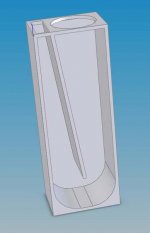
I to need a corner fitting solution and I have made a model of a retangular tall box that is close to what I want but it is to big. I need to find a way to put a TL similar to the picture below into a shape something like this.
Actually, this is the design I was fooling around with when I came up with the Darth Vader looking cabinet. But I think that the single bend TL with the terminus close to the driver would be the ideal to shoot for.
Hezz
A tapered triangular cross section would possibly be ideal for supressing standing waves in the pipe since there are no parallel walls.
I to need a corner fitting solution and I have made a model of a retangular tall box that is close to what I want but it is to big. I need to find a way to put a TL similar to the picture below into a shape something like this.
Actually, this is the design I was fooling around with when I came up with the Darth Vader looking cabinet. But I think that the single bend TL with the terminus close to the driver would be the ideal to shoot for.
Hezz
Attachments
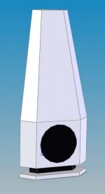
Here is a model of what I think is the best performing of the TL types for a subwoofer. This was the only topology that has the 100 Hz suckout instead of the giant 100 Hz peak.
It could be made either a top firing or a bottom firing speaker with the right pedestal.
Hezz
It could be made either a top firing or a bottom firing speaker with the right pedestal.
Hezz
Attachments
That design can be improved by making it triangulated... the internal baffle is set at a diagonal.
This one was designed for a midbass (the reason for the complication at the top.
This one is Bailey's 2-fold TTL (stepped taper)
http://www.t-linespeakers.org/design/foldings/tttl.html
The attached working drawing is for a Jordan JX125 TTL. Note the driver offset -- that is one great tool not used in Hezz's TL or either of the 2 lines above.
dave
This one was designed for a midbass (the reason for the complication at the top.
An externally hosted image should be here but it was not working when we last tested it.
This one is Bailey's 2-fold TTL (stepped taper)
http://www.t-linespeakers.org/design/foldings/tttl.html
An externally hosted image should be here but it was not working when we last tested it.
The attached working drawing is for a Jordan JX125 TTL. Note the driver offset -- that is one great tool not used in Hezz's TL or either of the 2 lines above.
dave
Attachments
Planet10,
Can you give me a brief synopsis of the advantage of the offset speaker placement. I know King's latest model can accomodate modeling for offset driver placement but none of the measured test setups in the Loudspeaker Design Cookbook based on Augsburger (sorry if spelling wrong) are done with an offset driver.
I'm thinking that with an offset driver the TL would behave like two different pipe lengths because some of the sound wave would move towards the closed end of the pipe and then bounce back towards the open end behaving like a longer pipe with a reversal direction.
I have an old version of MathCAD but don't really use it much so I don't know if King's MathCAD worksheets will work in my old version. Also I'm not anxious to go and study the MathCAD manual. Does King's alignment table methods work with offset drivers.
By the way thanks for the drawings and this seems like a very good way to create internal TL pipe. I saw another design similar to this on the transmission line web site. I think I need to go and try to do some problem solving to get something similar into my favored corner cabinet design.
Hezz
Hezz said:Can you give me a brief synopsis of the advantage of the offset speaker placement. I know King's latest model can accomodate modeling for offset driver placement but none of the measured test setups in the Loudspeaker Design Cookbook based on Augsburger (sorry if spelling wrong) are done with an offset driver.
I'm thinking that with an offset driver the TL would behave like two different pipe lengths because some of the sound wave would move towards the closed end of the pipe and then bounce back towards the open end behaving like a longer pipe with a reversal direction.
That is how it works... the driver is positioned so that the wave going towards he closed end cancels the 1st undesired line harmonic. You get a bit less strength in the primary resonance, but that is usually more than made up for because you can get away with less damping because you aren't tring to use it to kill that 1st undesired resonance.
I have an old version of MathCAD but don't really use it much so I don't know if King's MathCAD worksheets will work in my old version.
You don't really need to know how to use MathCAD to run the worksheets... you just need to put up with MathCADs UI to input a few numbers. I'm using the Explorer Verion of 8, own a copy of 7 and also a copy of V6 for the Mac.
I saw another design similar to this on the transmission line web site.
Those pics are off my TL site, so are likely the exact drawings you are thinking of 🙂
dave
Dave,
Thanks for the information. By the way, love your website.
I think my Mathcad version is something like v.3 or v.4. I will have to check it out.
Hezz
Thanks for the information. By the way, love your website.
I think my Mathcad version is something like v.3 or v.4. I will have to check it out.
Hezz
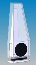
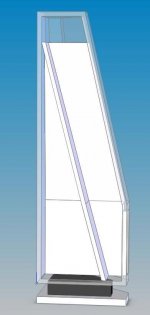
Here are a couple of solid model workups for the above corner enclosure. Maybe something like this would not make a bad subwoofer. There is some wasted space in the enclosure but it looks kind of cool.
I have made some of the walls partially transparent so that the inner TL partition can be seen. Using either a smaller driver or a bigger cabinet the driver could be moved up somewhat for an offset driver mounting position. The first main chamber is kind of triangular in shape but makes some variation for design asthetics.
Hezz
Attachments
Ya, Me too.
We use to have this fake electric wood burning stove from sears. It mounted in the corner and was shaped kind of like this. Believe it or not this shape is dictated completed by physical constraints. The only place I have to put the subwoofer is in a corner behind a keyboard rack that is positioned at a 45 degree angle at the corner of the room. A window ledge near the corner requires the taper so it doesnt' interfere with blinds and drapes.
This thing will tuck behind the keyboard rack and except for the top part sticking up will be completely hidden. OF course if it ever does become exposed I may have to put a small mural on it or something to make it blend in.
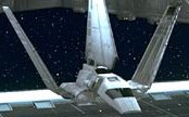
To bad I have no artistic painting skills. Still it does kind of look like the nose of a small imperial transport. So we still have a bit of the Star Wars theme.
Hezz
We use to have this fake electric wood burning stove from sears. It mounted in the corner and was shaped kind of like this. Believe it or not this shape is dictated completed by physical constraints. The only place I have to put the subwoofer is in a corner behind a keyboard rack that is positioned at a 45 degree angle at the corner of the room. A window ledge near the corner requires the taper so it doesnt' interfere with blinds and drapes.
This thing will tuck behind the keyboard rack and except for the top part sticking up will be completely hidden. OF course if it ever does become exposed I may have to put a small mural on it or something to make it blend in.
To bad I have no artistic painting skills. Still it does kind of look like the nose of a small imperial transport. So we still have a bit of the Star Wars theme.
Hezz
Hezz you design is getting to be very interesting. i like it! 🙂
Does not conventional wisdom state that corners are suppose to be the worst place to put a sub as it will excite all the room nodes? How do intend to tackle that?
Does not conventional wisdom state that corners are suppose to be the worst place to put a sub as it will excite all the room nodes? How do intend to tackle that?
Rademakers said:No, if you would do that, you would get a backloaded horn.
This is a TL, different design.
Mvg Johan
Ah, gotcha. Thats what the difference is. Still learning

- Status
- Not open for further replies.
- Home
- Loudspeakers
- Subwoofers
- Building the Darth Vader Corner Sub