I have spent perhaps the last three months modeling different subwoofer configurations to build into a corner type cabinet for my DIY home theater. I have had as my goal deep but very fast and non boomy base response. At first I wanted to use a single twelve in a critically damped sealed enclosure but I wanted more deeper reach. So then I thought about a 15 inch driver in a butterworth vented box.
This had been my best design until I realized that what I really wanted was a TL. A properly designed TL has all the attributes that I wanted in a sub except one. A large cabinet. I had pretty much decided that to accomplish what I wanted I needed a relatively large cabinet and since the corner placement allowed for this I should proceed.
My first designs were cool looking 7 foot tall tapered TL's which should have performed very well but I just felt that I didn't want to put that much cabinet into the room as the size would dominate everything.
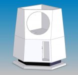
After much though I finally came up with this design. It is meant to get the most possible performance out of the 15 inch single driver that is possible without a giant horn enclosure. The shape looks so much like Darth Vaders helmut that I call it the Darth Vader Sub. How fitting as this corresponds to the imminent release of Star Wars Episode 3.
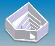
Here are a couple of rough solid models. It is a two piece affair with the tapered TL in the lower cabinet. THe cabinets seperate so that the TL can be easily fine tuned with stuffing. THe upper cabinet is small enough to be easier to build and make very resonance free with significant bracing.
And the beauty of it is that I could upgrade the driver to a more expensive high quality long x-mas subwoofer in the future more easily than a vented alignment because speaker parameters do not need to be quite so exact.
The upper box is shown without the top and internal bracing as I havent designed that far. The speaker is not quite a classic TL in that the Tl initial area is maybe only 70 -80 percent of the driver cone area. But since the primary driver box is larger than usual for a TL design I think that it will work well. It is kind of a hybrid TL.
Hezz
This had been my best design until I realized that what I really wanted was a TL. A properly designed TL has all the attributes that I wanted in a sub except one. A large cabinet. I had pretty much decided that to accomplish what I wanted I needed a relatively large cabinet and since the corner placement allowed for this I should proceed.
My first designs were cool looking 7 foot tall tapered TL's which should have performed very well but I just felt that I didn't want to put that much cabinet into the room as the size would dominate everything.
After much though I finally came up with this design. It is meant to get the most possible performance out of the 15 inch single driver that is possible without a giant horn enclosure. The shape looks so much like Darth Vaders helmut that I call it the Darth Vader Sub. How fitting as this corresponds to the imminent release of Star Wars Episode 3.
Here are a couple of rough solid models. It is a two piece affair with the tapered TL in the lower cabinet. THe cabinets seperate so that the TL can be easily fine tuned with stuffing. THe upper cabinet is small enough to be easier to build and make very resonance free with significant bracing.
And the beauty of it is that I could upgrade the driver to a more expensive high quality long x-mas subwoofer in the future more easily than a vented alignment because speaker parameters do not need to be quite so exact.
The upper box is shown without the top and internal bracing as I havent designed that far. The speaker is not quite a classic TL in that the Tl initial area is maybe only 70 -80 percent of the driver cone area. But since the primary driver box is larger than usual for a TL design I think that it will work well. It is kind of a hybrid TL.
Hezz
Attachments
I can't speak to the how it will sound, since I have no experience with transmission lines, but it certainly looks good. The greatest part about DIY is if it doesn't end up sounding right, you can always tweak or rebuild it. Good luck.
Very nice design work, a subwoofer idea after my own heart. I love building stuff like that, whish I had thought of such.
That is one of the coolest ideas I have ever seen! :thumb:
I just bought an AV15 on the blowout deal and have been looking for a sub idea that I can put in our living room. Until now the Ottoman sub has been tops, but this gives me another option.
I just bought an AV15 on the blowout deal and have been looking for a sub idea that I can put in our living room. Until now the Ottoman sub has been tops, but this gives me another option.
Vader?
Sweet,
but I'm going to have to disagree slightly. I'm seeing more small droid - angular R2D2ish - than vaders helmet.
Should put out just enough bass to simulate an exploding Death Star for sure though 😀 .
Cheers
AJ
Sweet,
but I'm going to have to disagree slightly. I'm seeing more small droid - angular R2D2ish - than vaders helmet.
Should put out just enough bass to simulate an exploding Death Star for sure though 😀 .
Cheers
AJ
Ya OK, I can go there. I have to admit the shape is a little bit up for interpretation.
I'm thinking that this shape could also work well with a double chamber reflex design with a few adjustments to the box sizes and volumes.
Hezz
I'm thinking that this shape could also work well with a double chamber reflex design with a few adjustments to the box sizes and volumes.
Hezz
Hi Hezz,
I built a sub, designed for a 20 Hz fundamental using a 10" driver, and though my test system showed clear output centered on 20, there was virtually no output due to the number of bends that were there (from what I presume). The enclosure was close to a cube in geometry (I ran the line back from the driver up over top of it, to the left, back, down, forward, up, forward, down, and then forward).
It was a disappointing result, and no sim work will help you out in this respect (being able to plan for reduced output due to bending).
Presumably from your SolidWorks work (is that right?), you'll be able to CNC the pieces for the enclosure easily, assemble, and test your theory. I hope it works out.
Brendon
I have a dumb question, but isnt the horn suposed to be going the other way? With it getting wider rather than narrower towards the opening?
No, if you would do that, you would get a backloaded horn.
This is a TL, different design.
Mvg Johan
This is a TL, different design.
Mvg Johan
Brendon,
I believe you are right. What I am beginning to glean from my studies is that the TL's that have a lot a deep bass slam are based on straight or single tapered pipes. As you say the acoustic impeadace is very high in this TL design due to too many turns and discontinuities. It is likely that it would sound very good but not give the strong low bass that I would like.
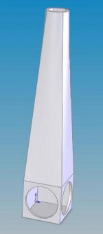
I made a much simpler design which should kick butt in the bass department but after looking at the model I don't know if I can live with that 7 foot tall thing. Even though it doesn't take up much room in the corner. Here is a picture. It uses dual 15 inch drivers in out of phase push pull wiring. Also it would be hard to build but I think it could be done out of foam and fiberglass and still not be too heavy.
In this model there is an approximate 1:4 taper which is said to be ideal for strong bass but since there are two drivers I wonder if the performance might be better if the taper was a little less as this thing will be moving a lot of air.
Hezz
I believe you are right. What I am beginning to glean from my studies is that the TL's that have a lot a deep bass slam are based on straight or single tapered pipes. As you say the acoustic impeadace is very high in this TL design due to too many turns and discontinuities. It is likely that it would sound very good but not give the strong low bass that I would like.
I made a much simpler design which should kick butt in the bass department but after looking at the model I don't know if I can live with that 7 foot tall thing. Even though it doesn't take up much room in the corner. Here is a picture. It uses dual 15 inch drivers in out of phase push pull wiring. Also it would be hard to build but I think it could be done out of foam and fiberglass and still not be too heavy.
In this model there is an approximate 1:4 taper which is said to be ideal for strong bass but since there are two drivers I wonder if the performance might be better if the taper was a little less as this thing will be moving a lot of air.
Hezz
Attachments
What I've heard is that the bends will not effect the line too much. I'd presume this to be true considering the very long wavelengths involved. But if you guys are getting different results... I dont know what to say.
Things very important in TL design from my experience are stuffing density, line cross section, and of course length. If those are good and you still have lack of output then I guess those bends are doing something!
Things very important in TL design from my experience are stuffing density, line cross section, and of course length. If those are good and you still have lack of output then I guess those bends are doing something!
the folds shouldn't make much difference, but to get bass you need an adequate cross-section...
I doubt the DV as 1st pictured is big enuff.
dave
I doubt the DV as 1st pictured is big enuff.
dave
Hezz: you should bend the 7 foot pipe once! You dont want the port firing at to far a distance from the woofer or you will get a uneven response and strange combfilter effects. It would probably be easier to live with to.
Otherwise a very nice design. Go for it! Should give you as much bass you can put up with.
Otherwise a very nice design. Go for it! Should give you as much bass you can put up with.
I think the cross sectional area in the first design is a problem but when I look at the measurements and graphs in the speaker design cookbook it is quite obvious that any bends have a significant effect on the bass. The fewer the better and my guess is that up to three is acceptable. THe output close to the driver is another issue but I can't get past the style issue of bending the thing to come back down.
Obviously it would be better if the output of the TL were near the driver but it seems that many sucessful designs have it a long way away. I am going to rethink this and see if I can get it with one bend. Then I can make the TL a bit longer too.
I think I am going to look more closly at those double sonotubes TL's. They are pretty interesting.
Hezz
Originally posted by Hezz
He output close to the driver is another issue but I can't get past the style issue of bending the thing to come back down.
A folded tapered line fits nicely inside any regular cylinder...
dave
After looking more closely at the response charts for the one fold tapered TL it seems to have some very good traits. High output in the low bass and the usual big spike around 100 Hz is a suckout instead. This is perfect for a sub since we don't want it operating much above 100 Hz anyway.
I am starting to lean towards a standard tall rectangular box about five feet tall with a one fold tapered TL. Large cross section at the speaker end. IF this topology doesn't have the big spike around 100 Hz it would not need as much stuffing thereby making it more efficient.
Hezz
I am starting to lean towards a standard tall rectangular box about five feet tall with a one fold tapered TL. Large cross section at the speaker end. IF this topology doesn't have the big spike around 100 Hz it would not need as much stuffing thereby making it more efficient.
Hezz
I have downloaded most of King's materials and read about a third of them. But I'm trying to come up with a basic topology from information from Augsburgers methods in the Loudspeaker Design Cookbook first.
Once I have decided on a basic topology then I will try to optimize the line length and taper based on the driver and some of King's models.
I made some pencil sketches and I think I have a basic design. But I want the TL to taper in two dimensions to reduce standing waves in the line so I'm going to model a slightly tapered enclosure.
ALso if you look in Loudspeaker Design Cookbook there is one line stuffing method that in particular has a extended and flat frequency response. In particular it requires that the line is not fully stuffed but allows air to move more freely in the line. The damping material is centered in the line but there is a free air space left of a couple of inches around the damping material.
My idea is to line all the walls with thick felt and then place the damping plugs inside. The damping plugs will be made in exact shapes by sewing open weave speaker grill material into shapes and then stuffing them with dacron or whatever is used. Then the dampers will be suspended in the line so that they are centered in the line but leave a free flowing air space around them near the inner wall boundries of th line.
Hezz
- Status
- Not open for further replies.
- Home
- Loudspeakers
- Subwoofers
- Building the Darth Vader Corner Sub