jneutron said:
(OH well..so much for the HTML code..)
Well, willya lookit that, some kind soul edited your post to fix the code!
This software recognizes square brackets, not the official HTML <>.
SY said:
Well, willya lookit that, some kind soul edited your post to fix the code!
This software recognizes square brackets, not the official HTML <>.
I sit in awe..thanksthanksthanks cool
Cheers, John
12/3 SJTW sounds like good old extension cord to me. The stuff I was thinking of is supposed to remain flexible when being used outside in below 0 degrees Celsius conditions. Ive never heard any claims for its performance between 2.1 and 4.7 K. (had to look that up)
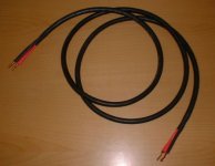
Either way, it looks great with the Speakerons.
Either way, it looks great with the Speakerons.
Da5id4Vz said:12/3 SJTW sounds like good old extension cord to me. The stuff I was thinking of is supposed to remain flexible when being used outside in below 0 degrees Celsius conditions. Ive never heard any claims for its performance between 2.1 and 4.7 K. (had to look that up)
Either way, it looks great with the Speakerons.
I love the neutrik speakons..my amps came with them, so I built and adapted all my gear to handle them.
The cord is exactly good old extension cord. I was walking through Sams club, and they screamed at me from the display...17 dollars for a 90 foot cord..so I bought 2 greens, 1 purple, 2 oranges, and two yellows...and no regrets.
My work involves 1.8K and 4.5K. Has to do with NiTi capability at 3.5 Tesla and 7T. Some of the wires have to remain flexible at that temp, limiting us to kapton and tefzel.
Cheers, John
PS...using the square brackets for html code is much easier than using those <>'s...don't need the shift key..
I guess 2x14ga is like 11Ga. $0.47/ft seems like an ok price.
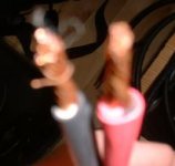
You can see (bairly) how that I paired up the conductors like TNT-Audio's Star wire thingy.
http://www.tnt-audio.com/clinica/star.html
You can see (bairly) how that I paired up the conductors like TNT-Audio's Star wire thingy.
http://www.tnt-audio.com/clinica/star.html
Attachments
Re: Re: Re: my double braid cable
The equations have already been figured out for coaxial cable:
L = (u/2*pi) * ln(D/d)
C = (e*2*pi) / ln(D/d)
u = 4 * pi * 10^-7 H/m
e = 2 * 10^-11 pf/m * relative permittivity
D = inner diameter of shield
d = outer diameter of core
Of course, you don't get something for nothing: lower inductance gained by geometry is counterbalanced by higher capacitance. It all comes down to what tradeoff you want to make.
Francois.
jneutron said:
Thanks. But I'm posting to GET ""my *****ing""...IOW, the opinion of others.. so don't apologize...
Inductance is the measure of the amount of energy stored in the magnetic field as a result of current.. For any wire it is the sum of the internal energy stored by the internal inductance...and the external storage, which is the mag field outside the conductor.
The internal braid was used to remove the internal inductance..
[...]
The characteristic inpedance of the overall will, as you point out, be dependent on both L and C, as will prop speed. But this cable experiment is designed first to minimize inductance at all cost (cost being dielectric withstanding between conductors). And then, after test verification of models by using various sizes and dielectrics, coming up with general equations for L and C and how they relate to the sizes of the conductors and the dielectric type and thickness.
Cheers, John
The equations have already been figured out for coaxial cable:
L = (u/2*pi) * ln(D/d)
C = (e*2*pi) / ln(D/d)
u = 4 * pi * 10^-7 H/m
e = 2 * 10^-11 pf/m * relative permittivity
D = inner diameter of shield
d = outer diameter of core
Of course, you don't get something for nothing: lower inductance gained by geometry is counterbalanced by higher capacitance. It all comes down to what tradeoff you want to make.
Francois.
Re: Re: Re: Re: my double braid cable
Hmmm...just found a link..
http://www.sigcon.com/lib/htm/coax.htm
they have L=length * 5.08*10-9*ln(D/d)
If I use yours, I get 30 nanohenry per...AHA there's the problem...yours is henries per meter...
So, we got the same...about 9 to 10 nanohenries per foot..checks out..correlates quite well to the measured results.
Thanks..
Yah, definite tradeoff L and C..I'll put together a spreadsheet with all the info, and try a few more geometry data points for completeness..
In the meantime, I'm preparing to give the cable I made to a friend who claims to hear the differences..
What I hadn't realized before...the characteristic Z of this cable is in the 4 to 8 ohm region..purely by accident..
Cheers, John
DSP_Geek said:
The equations have already been figured out for coaxial cable:
L = (u/2*pi) * ln(D/d)
C = (e*2*pi) / ln(D/d)
u = 4 * pi * 10^-7 H/m
e = 2 * 10^-11 pf/m * relative permittivity
D = inner diameter of shield
d = outer diameter of core
Of course, you don't get something for nothing: lower inductance gained by geometry is counterbalanced by higher capacitance. It all comes down to what tradeoff you want to make.
Francois.
Hmmm...just found a link..
http://www.sigcon.com/lib/htm/coax.htm
they have L=length * 5.08*10-9*ln(D/d)
If I use yours, I get 30 nanohenry per...AHA there's the problem...yours is henries per meter...
So, we got the same...about 9 to 10 nanohenries per foot..checks out..correlates quite well to the measured results.
Thanks..
Yah, definite tradeoff L and C..I'll put together a spreadsheet with all the info, and try a few more geometry data points for completeness..
In the meantime, I'm preparing to give the cable I made to a friend who claims to hear the differences..
What I hadn't realized before...the characteristic Z of this cable is in the 4 to 8 ohm region..purely by accident..
Cheers, John
OH...one more thing.
The equations for L in a coax work very well when the skin effect is neglected..in other words, the equation assumes that the frequency of interest is high enough that the central conductor is a shell of current.
For a center wire, that is not so..and, for audio frequencies, the skinning is not great enough to remove that internal inductance.
So, the equation will be in error in the amount of 15 nanohenries per foot within the audio range..
I will also be testing that with a new cable construct to verify that is indeed the case.
Cheers, John
cable calculator nomographs
Planted inductance and capacitance calculations into an excel spreadsheet. Here are the first graphs for the braid in braid. I set a limit on capacitance so that the graph didn't compress too heavily.
For my first wire, the dielectric was 10 mils, L measured 9 to 16 (error in lsb), and capacitance was 288 pf per foot. just above the limit in my graph.
Attachments
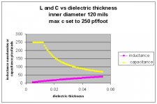
and here is the L and C for different inner braid diameters, with the dielectric tefzel fixed at 10 mils..This is the tradeoff graph for inductance vs capacitance for one dielectric thickness.
I don't yet know how to force excel into a 3-d plot to give L and C plotted against diameter and insulation thickness...yet, anyway..
OH...BTW, I accidentally put microhenries as the x axis label..it should be nanohenries per foot
Cheers, John
I don't yet know how to force excel into a 3-d plot to give L and C plotted against diameter and insulation thickness...yet, anyway..
OH...BTW, I accidentally put microhenries as the x axis label..it should be nanohenries per foot
Cheers, John
Attachments
update
By inspection..the following..
Coax cable will have an L-C relation, dependent on dielectric..
The equation is:
L * C =1031 * DC
L inductance per foot in nanohenries
C capacitance per foot in picofarads
DC is dielectric constant.
For a DC of 2.7, tefzel, for example...
Choose L to be 50 nanohenries per foot, with tefzel insulation....
C will be: (1031 * 2.7) / 50
or...55.67 picofarads per foot.
Choose L = 100 nH... C =27.83 pf per foot.
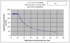
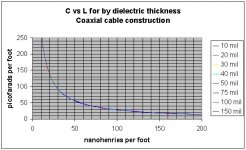
In plotting C vs L for inner braid sizes from 10 mils to half an inch, this plot emerged, with all the different insulation thickness l-c curves overlapping..
Cheers, John
By inspection..the following..
Coax cable will have an L-C relation, dependent on dielectric..
The equation is:
L * C =1031 * DC
L inductance per foot in nanohenries
C capacitance per foot in picofarads
DC is dielectric constant.
For a DC of 2.7, tefzel, for example...
Choose L to be 50 nanohenries per foot, with tefzel insulation....
C will be: (1031 * 2.7) / 50
or...55.67 picofarads per foot.
Choose L = 100 nH... C =27.83 pf per foot.
In plotting C vs L for inner braid sizes from 10 mils to half an inch, this plot emerged, with all the different insulation thickness l-c curves overlapping..
Cheers, John
Attachments
- Status
- Not open for further replies.
- Home
- Loudspeakers
- Multi-Way
- building speaker cable