Hi Steve,

I mean Bmax here. For Amidon F power ferrite Bsat = 4700 Gauss (at 10 Oer.) So I don`t wont to operate close to this value...
So noise & spikes in output voltage are impossible to avoid ?
Output voltage can be seen on screenshots, I marked with red color what I mean.
I`ll try to add snubbers across secondary to eliminate these spikes .
Luka,
But you used both input / output inductors in you 12V SMPS project...
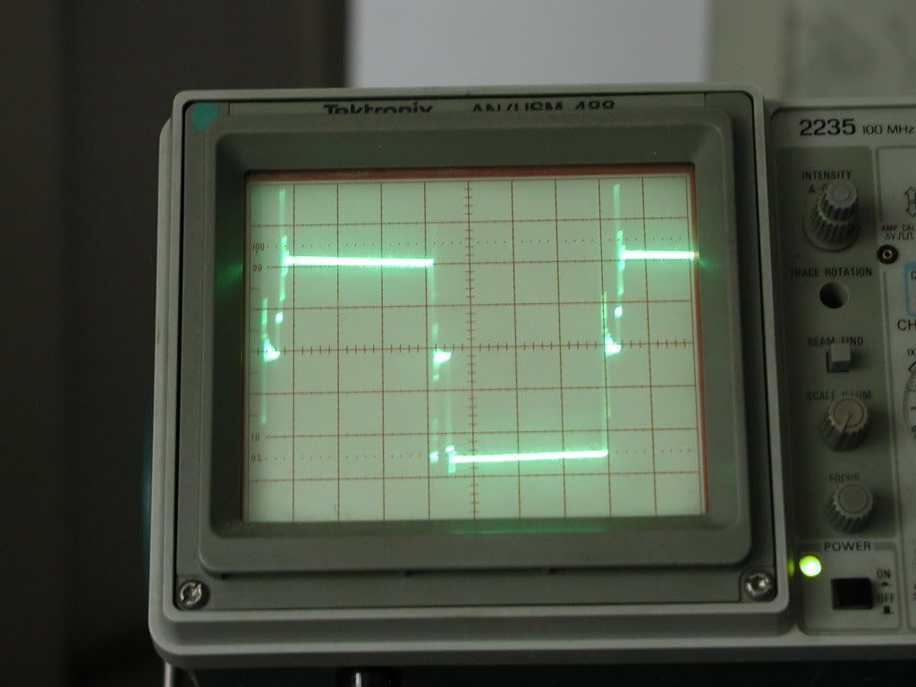
GUYS, can you to share some of you screenshots from well loaded SMPS trafo`s primary, & output voltage please ?
😀 😀 😀 😀 😀 😀Cheap - Cheap! (Did I hear a birdie somewhere?!?!)
At 30-50kHz, a 4T + 4T primary is usually OK. For your B value of 2000G, is this your B(max) or B(sat)? B(max) is the number you want to work with for calculating under normal operating, and B(sat) is the never-to-exceed value (this is essentially the point of core saturation).
I mean Bmax here. For Amidon F power ferrite Bsat = 4700 Gauss (at 10 Oer.) So I don`t wont to operate close to this value...
Waveforms look pretty good.
So noise & spikes in output voltage are impossible to avoid ?
Output voltage can be seen on screenshots, I marked with red color what I mean.
I`ll try to add snubbers across secondary to eliminate these spikes .
Luka,
for high efficiency, less parts, easyer to make and they work great
But you used both input / output inductors in you 12V SMPS project...
GUYS, can you to share some of you screenshots from well loaded SMPS trafo`s primary, & output voltage please ?
Attachments
Hi
Yes I did, on smaller one(300w, probably limited by other smps, which has ~12.5v on output at that time), but that was regulated, on big one I don't have nor for input nor for output.
Like I said aim for freq around 30kHz or lower, and from what I can see, your snubbers aren't good enough and you probably have big dead time...less dead time will (I think) result in less oscilations...but I would fix snubbers first.
What value do you have and from where to where?
Luka,
The formula that I used:
..................(2/Fsw)*Dmax*(Vin min - Vds on)
N turns = ------------------------------------------- *10^6
...........................Acore*Bmax*2
whwre: Fsw in Hz
Dmax for single pulse (</= 50%)
Acore in cm^2
Bmax in Gauss
So I used 2000 Gauss from zero to Bmax to get number of primary turns... Is I should to use value from Bmin to Bmax (4000 Gauss) here ?
Yepp, I didn`t setted up snubber yet, just placed it to see is it able to help. Now I got sweet set of multilayer ceramic caps, so next weekend I`ll play around fixing snuber. Else I think to rewind trafo`s secondary with 2 18AWG wires instead 1 18AWG...
I mean from zero to Bmax.What value do you have and from where to where?
The formula that I used:
..................(2/Fsw)*Dmax*(Vin min - Vds on)
N turns = ------------------------------------------- *10^6
...........................Acore*Bmax*2
whwre: Fsw in Hz
Dmax for single pulse (</= 50%)
Acore in cm^2
Bmax in Gauss
So I used 2000 Gauss from zero to Bmax to get number of primary turns... Is I should to use value from Bmin to Bmax (4000 Gauss) here ?
Like I said aim for freq around 30kHz or lower, and from what I can see, your snubbers aren't good enough and you probably have big dead time...less dead time will (I think) result in less oscilations...but I would fix snubbers first.
Yepp, I didn`t setted up snubber yet, just placed it to see is it able to help. Now I got sweet set of multilayer ceramic caps, so next weekend I`ll play around fixing snuber. Else I think to rewind trafo`s secondary with 2 18AWG wires instead 1 18AWG...
You seem to be new to the SMPS design game.
About output spikes:
Be quite careful, what you see on the scope may not be there. Short the scope probe ground lead to the probe input. Lay the probe near where you measure the spikes. If the spikes are still there, then the scope probe cable or scope AC power cord is acting as an antenna. The scope is displaying a signal that's not present in the conventional sense across the probe/ground input.
Hi
I mean sunubbers...ok anyway just tried my again, 12.2v in ta CT, 87.7v out @ 230w
Pri

sec

3x1mm, 6 turns for pri, 1x1mm, unknown turns for sec, I guess about 23... it is a bit odd I did get 300w but I not sure it with this core setup, and a bit big dead time for my taste, lol don't know how that happened...any pic are here
I mean sunubbers...ok anyway just tried my again, 12.2v in ta CT, 87.7v out @ 230w
Pri
sec
3x1mm, 6 turns for pri, 1x1mm, unknown turns for sec, I guess about 23... it is a bit odd I did get 300w but I not sure it with this core setup, and a bit big dead time for my taste, lol don't know how that happened...any pic are here
Hermanv,
I`ll try to check my scope as you suggested, but I`m not sure that original 200MHz Tektronix probes are good antennas. Will see.
Luka,
Thank`s so much for the pics. Now I have an axample of what I should to get. It`s seems to be that Tektronix scopes are DIYer`s favorite choise.🙂
Yes, you right , but to begin to do something from zero, & learn by mistakes much better than to avoid mistakes by doing nothing...😉You seem to be new to the SMPS design game.
I`ll try to check my scope as you suggested, but I`m not sure that original 200MHz Tektronix probes are good antennas. Will see.
Luka,
Thank`s so much for the pics. Now I have an axample of what I should to get. It`s seems to be that Tektronix scopes are DIYer`s favorite choise.🙂
Hi
Sure is 😀. Get it better then I did, then you will know you got it right, but your got it pretty good even now
Sure is 😀. Get it better then I did, then you will know you got it right, but your got it pretty good even now
Hello guys, 😉
Seems to be that I found solution for regulated version of my SMPS🙂 🙂 🙂 . I added inductor between diode bridges & output caps, & placed the transisent voltage supressors across primary windings. See cshematic.
The result: output voltage absolutley flat , without any spikes, glitches and other garbage 😀
  .
.
Now some about my expiriments.
First I played around output inductor. I inded 2 different inductors - first about 2x24 turns of 18AWG wire on toroid extracted from old PC SMPS, second winded on ferrite torroid from http://www.tscinternational.com/tscwebcat2007.html , material- ASTM P7070, size OD25mm ID 16mm H8mm , Al = 1724. It contain 2x17 turns of 18AWG wire - i`ts around 50uH.
With first, PC inductor , SMPS produsing some acustical noise when loaded. At 210W load, noise louder than at 320W. MOSFETS are cool without heatsinks even at maximal load.
With second inductor (50uH) there are almost no noise, but MOSFET`s are became very hot within seconds at 210-320W load. 😕
Without inductor , regulated SMPS - output voltage full of big spikes, 2 MOSFET`s are destroyed by overheating
Anybody can to explain me a nature of the process above please - why heat dissipaton on MOSFET`S is so different ??? How to calcuate the exect value of output inductor ?
Generally, after adding inductor, the output voltage became almost ideal, just very small, almost invisible spikes were occured.
After adding the transisent voltage supressors , output voltage became absolutley clean and flat 🙂
Now I`m planing to try to fix my snubbers - may be I`ll be able
to eliminate the transisent voltage supressors from schematic...
As Herman mentoined the probes of the scope are able to catch EMI from SMPS... Very possible. I cheked my probes in several differet ways - placed near loaded SMPS, connected ground only to MOSFET`s drains , etc. Yes, probes are able to catch some RF EMI, but the original 200MHz Tektronix probes are very poor antenas
😉 The spikes at output were here, these disappeared after I added the inductor, not after I replaced my probes with GHz rated, $500...700 set.🙂
hermanv - very good note about measurement equipment, without high quality stuff realy possible to start to hunt ghosts.
Many thanks to all guys who helped me with power stage: Luka, Steeve (aka N-Channel), Perry Babin, hermanv ,djQUAN, and others.
But project not finished yet, next stage will be qurrent mode controller ... Stay tuned😉
Seems to be that I found solution for regulated version of my SMPS🙂 🙂 🙂 . I added inductor between diode bridges & output caps, & placed the transisent voltage supressors across primary windings. See cshematic.
The result: output voltage absolutley flat
, without any spikes, glitches and other garbage 😀 . Now some about my expiriments.
First I played around output inductor. I inded 2 different inductors - first about 2x24 turns of 18AWG wire on toroid extracted from old PC SMPS, second winded on ferrite torroid from http://www.tscinternational.com/tscwebcat2007.html , material- ASTM P7070, size OD25mm ID 16mm H8mm , Al = 1724. It contain 2x17 turns of 18AWG wire - i`ts around 50uH.
With first, PC inductor , SMPS produsing some acustical noise when loaded. At 210W load, noise louder than at 320W. MOSFETS are cool without heatsinks even at maximal load.
With second inductor (50uH) there are almost no noise, but MOSFET`s are became very hot
within seconds at 210-320W load. 😕 Without inductor , regulated SMPS - output voltage full of big spikes, 2 MOSFET`s are destroyed by overheating
Anybody can to explain me a nature of the process above please - why heat dissipaton on MOSFET`S is so different ??? How to calcuate the exect value of output inductor ?
Generally, after adding inductor, the output voltage became almost ideal, just very small, almost invisible spikes were occured.
After adding the transisent voltage supressors , output voltage became absolutley clean and flat 🙂
Now I`m planing to try to fix my snubbers - may be I`ll be able
to eliminate the transisent voltage supressors from schematic...
Be quite careful, what you see on the scope may not be there....
As Herman mentoined the probes of the scope are able to catch EMI from SMPS... Very possible. I cheked my probes in several differet ways - placed near loaded SMPS, connected ground only to MOSFET`s drains , etc. Yes, probes are able to catch some RF EMI, but the original 200MHz Tektronix probes are very poor antenas
😉 The spikes at output were here, these disappeared after I added the inductor, not after I replaced my probes with GHz rated, $500...700 set.🙂
hermanv - very good note about measurement equipment, without high quality stuff realy possible to start to hunt ghosts.
Many thanks to all guys who helped me with power stage: Luka, Steeve (aka N-Channel), Perry Babin, hermanv ,djQUAN, and others.
But project not finished yet, next stage will be qurrent mode controller
... Stay tuned😉Attachments
Hi
There is still one more thing you can do, replace suppresors with fast diode and link them to input caps, so from D conducting to input caps. If voltage on D will be higher then on caps, diode will conduct, and D will have voltage ~ the same as on input caps.But do use very fast diods, and probably one that can counduct more then just mA
With PC inductor looks better, more inductance?
PS: Regulation needs output inductor and D.C. must never go max. or you lose regulation, and you will have some voltage on inductor at that time, so output will already start to fall
PS2:If you have your output inductor like you havve it on schema it is wrong, one dot should be on other end, so you would need to wind it right. That is common mode, so current going to + makes flux in same direction then current going from - to inductor
Hi Luka,
If I understand you correct, you are about to add D7 & D8 (see schematic) ?
Are schottky diodes with Trr<35ns suitable for such application ?
Yes, it contain toroid of almost same size , and more turns of wire - 24..27.
I`ll try what you suggested...
There is still one more thing you can do, replace suppressors with fast diode and link them to input caps, so from D conducting to input caps. If voltage on D will be higher then on caps, diode will conduct, and D will have voltage ~ the same as on input capacity do use very fast diodes, and probably one that can counduct more then just mA
If I understand you correct, you are about to add D7 & D8 (see schematic) ?
Are schottky diodes with Trr<35ns suitable for such application ?
With PC inductor looks better, more inductance?
Yes, it contain toroid of almost same size , and more turns of wire - 24..27.
PS2:If you have your output inductor like you havve it on schema it is wrong, one dot should be on other end, so you would need to wind it right. That is common mode, so current going to + makes flux in same direction then current going from - to inductor
I`ll try what you suggested...
Attachments
Hi
Yes D7,D8 just like that, you will just have to find some good diods what will work under those conditions
About 2nd PS, you can use 2 seperate inductors, you don't need both coils to be on same core, but that was is better, one rail tracks better other one
And you Rg could be higher, you really don't need that fast fets to be, 22R would be as far as oscilations go, better, and heat won't be that higher, in other words, you won't even know the diffrence
And you have high input capacitance, are you making multi kw smps? If not, you could use half that and save space...
Hi Luka,
As we here in Israel have holiday, I am able to make my experiments , & respond fast 😀
I tried to reconnect the inductor. The result - regulation was destroyed 😕 While inductor connected as before, there is equal voltage on both output caps - 39.3V , 78.6V total.
While inductor connected as you told, total voltage the same - 78.6V, but if I placing the load to one rail only, it falls to about 10V...15V, other rail rising such way, that total kept the same -78V. Even when I disconnecting load, voltages don't coming back to be equal...😕
Next, I tried to rewind my TSC based inductor, to add several turns. Its became to preform just a little beat better than was.
MOSFET`s & the TRANSIL`s are still overheating very fast. When I placed PC inductor back, I`m able to hold my finger on any of 4 MOSFET`s, that just became just little warm without any heatsinks under contentious 320W load.
With diodes & Rg I didn`t tryed yet.
I agree that at Fsw= 25KHz , it`s possible to reduse Dv/Dt of MOSFET`s
And yeah I forgot to remoove spare caps from input bank, now 38200uF connected 😱 😱 😱 If to go with 50uf per 1W,
I need no more than 300*50= 15000uF.
Any body know from witch material are made the small yellow toroids that used in PC SMPS as output inductors ???
That is all good, you can't load just one and expect other one to stay the same, I told you to do that, if you have as load amp that draws from both rails, one rail could be loaded a bit more, but voltage will be the same(I think), but normal load is the same for both rails, so you can't really test if this works, at least I don't know how...While inductor connected as you told, total voltage the same - 78.6V, but if I placing the load to one rail only, it falls to about 10V...15V, other rail rising such way, that total kept the same -78V. Even when I disconnecting load, voltages don't coming back to be equal...
About the picture, you will be able to that that better then I from pic...Do you know the right hand rule? current one finger, magnetic field other(around wire),...? If you do, look how current is going from bridge in to inductorm see how that wire makes flux in core...then goes to + of output cap, load and you are at - caps(-39.xV) then that same current enters into other wire, and see if that one makes flux in core in same direction as first did...I hope you understand this...
Ps: from what I can tell from pic, you have it in diffrencial mode, flux cancels itself out, I use 2 wires in same direction, and cross one end of the wires so that you have looking from above
3****4
------------
|********|
------------
1 ****2
Ok let see now,... 1 is from bridge rect. +, 2 is - of it, 1 and 2 are those 2 wires that are ||, 3 goes to + caps, 4 to - caps
1 and 4 are start of wires that go || on core, 2 and 3 are their ends,
1 and 4 is the same wire, 2 and 3 is same wire(I hope I got this right)
Hi Luka,
I tried this way, result is in post above.
Whats wrong in using diffrencial mode inductor ?
Do yo know from wich material made cores of PC`s SMPS output inductors ? Is it iron powder ?
Yes, such way my SMPS working fine.Ps: from what I can tell from pic, you have it in diffrencial mode, flux cancels itself out,
I use 2 wires in same direction, and cross one end of the wires so that you have looking from above
3****4
------------
|********|
------------
1 ****2
Ok let see now,... 1 is from bridge rect. +, 2 is - of it, 1 and 2 are those 2 wires that are ||, 3 goes to + caps, 4 to - caps
1 and 4 are start of wires that go || on core, 2 and 3 are their ends,
1 and 4 is the same wire, 2 and 3 is same wire(I hope I got this right)
I tried this way, result is in post above.
Whats wrong in using diffrencial mode inductor ?
Do yo know from wich material made cores of PC`s SMPS output inductors ? Is it iron powder ?
Hi
Yea I think they are iron poweder. I did write several lines of text up to here, but you should read this, easyer to understand
http://www.murata.com/emc/knowhow/pdfs/te04ea-1/26to28e.pdf
http://www.butlerwinding.com/inductors/common-mode2.html
http://cktse.eie.polyu.edu.hk/NSR/presentation/SMPS-lecture-1.pdf
For other you can search the net
Hi Luka,
Yes, if inductor connected in differential mode everything is just great 😀 Transformer, inductor, all of semiconductors are running cool without heatsinks at any power. Its more than important in my country, where summer is so damn hot . I think that if inductor connected in differential mode, it acting as impedance between trafo + MOSFET`s to output caps + load. It saving output caps & MOSFETS from high current stress during MOSFETS turning on (front of each pulse). I think it making SMPS less effective, but I think that better to loose several % of effectiveness, than add more MOSFET`s, large & expensive heatsinks, cooling fans etc.😉
Try differential mode inductor yourself, may be you will like it 😉
Else I found good sourse of cores for output inductor - https://www.amidoncorp.com/items/36 These toroids are the same as used in PC`s SMPS, so I`m going to order a couple larger ones. These should to be very good for output chokes.
Yes, if inductor connected in differential mode everything is just great 😀 Transformer, inductor, all of semiconductors are running cool without heatsinks at any power. Its more than important in my country, where summer is so damn hot
. I think that if inductor connected in differential mode, it acting as impedance between trafo + MOSFET`s to output caps + load. It saving output caps & MOSFETS from high current stress during MOSFETS turning on (front of each pulse). I think it making SMPS less effective, but I think that better to loose several % of effectiveness, than add more MOSFET`s, large & expensive heatsinks, cooling fans etc.😉 Try differential mode inductor yourself, may be you will like it 😉
Else I found good sourse of cores for output inductor - https://www.amidoncorp.com/items/36 These toroids are the same as used in PC`s SMPS, so I`m going to order a couple larger ones. These should to be very good for output chokes.
Hi
And smps really don't need big heatsinks, not if they work ok, you could use case inside of which it will be for cooling and it should e enough
It is not suppose to, if you will load it a lot you could burn that choke, as it will act as barrier and I don't think you want that...it acting as impedance
And smps really don't need big heatsinks, not if they work ok, you could use case inside of which it will be for cooling and it should e enough
I don't think it was working that way, I think it was like I didn't put anything in...are you sure you even have it in differential mode ? 😉Try differential mode inductor yourself
- Status
- Not open for further replies.
- Home
- Amplifiers
- Power Supplies
- Building my first 12v smps...