I didn`t received core for current trafo.
Oh please! Does it worth to put in harms way your entire circuit? Couldn't wait for 2 weeks to get those CS toroids? Did you got the UC2825 already?
😀 UC2825 are here, just waiting for fixed power stage 
The cores will arrive shortly, but still be one not so simple task - differential feedback circuit...
But the only thing that I can`t to understand. - 99.9% of all car audio amplifiers stuffed with voltage mode push-pull SMPS, while current mode control is much more reliable & safe for this purpose.
So why voltage mode used in almost all cases ?
But the only thing that I can`t to understand. - 99.9% of all car audio amplifiers stuffed with voltage mode push-pull SMPS, while current mode control is much more reliable & safe for this purpose.
I really do not know for sure. But i have this explanation: Many of the folks doing designs in audio are basically audio amateures. Sometime, as i look upon various audio power amplifier schematics, i cant shake the feeling that the designer of the circuit wanted to "show-off" with his fancy analog design knowledge, creating monsterous shematics that actually do not work in the end.
Also look at the valve enthusiasts. They really think that a push-pull tube amplifier will easily outperform ANY solid state. I suggest it will easily outperform any poorly-designed solid state amp, and there are many bad schematics on the web and in various journals.
Switching Power supply design is a very professional area. One needs to know a LOT to design good and reliable power supplies. And when amateur audio PA designers need to create an accompaniying SMPS for their products, thats what you get. It actually works.... kinda.... untill it puffs with no explanation. And there they go: reconstruct a voltage mode push-pull with no inductor at the output of the rectifier. And it works... kinda...untill it puffs again, and again and again.
Most of the people designing these amplifiers don't have much understanding about SMPS. They use cookbock circuit receipes. The simplest and most usual one is the TL494 with soft start and fixed duty cycle driving two banks of MOSFETs, transformer and diodes.
This arrangement is actually very reliable because transformer leakage inductance is usually over 10uH (as seen from secondaries) resulting in no stress at all due to current peaks, but it *can't* be reliably regulated.
This arrangement is actually very reliable because transformer leakage inductance is usually over 10uH (as seen from secondaries) resulting in no stress at all due to current peaks, but it *can't* be reliably regulated.
Hello guys 🙂
Now I played around SPICE simulations of differential feedback circuit to determinate values for components. I noticed that that frequency bandwidth of feedback circuit going be too wide - it flat up to ulmost 100KHz... But it should not exceed 7-10% of Fsw.
I added C5 to schematic to manage bandwidth. Is it good idea, or better to manage feedback bandwidth after optocoupler ?
Once I readed some thread about SMPS here, at diyaudio. One guy suggesteg the following : "Just read the full design for making car amplifier from valveaudio site couple of times, and you will complete the smps."...
I readed all on website that was suggested couple of times. Else I readed other datasheets, appnotes, books, websites - couple of times each one, and time after time I came across same idea - POWER ELECTRONICS IS A UNIVERSE & need to spent years of learning, & lot of burned components, just to begin to understand whats going on here.
Now I played around SPICE simulations of differential feedback circuit to determinate values for components. I noticed that that frequency bandwidth of feedback circuit going be too wide - it flat up to ulmost 100KHz... But it should not exceed 7-10% of Fsw.
I added C5 to schematic to manage bandwidth. Is it good idea, or better to manage feedback bandwidth after optocoupler ?
Switching Power supply design is a very professional area. One needs to know a LOT to design good and reliable power supplies.
Once I readed some thread about SMPS here, at diyaudio. One guy suggesteg the following : "Just read the full design for making car amplifier from valveaudio site couple of times, and you will complete the smps."...
I readed all on website that was suggested couple of times. Else I readed other datasheets, appnotes, books, websites - couple of times each one, and time after time I came across same idea - POWER ELECTRONICS IS A UNIVERSE & need to spent years of learning, & lot of burned components, just to begin to understand whats going on here.
Attachments
Hello guys,
Now I tested the prototype of current trafo. As always, I started from doing mistake 🙂 - I placed whole turn for primary. So my trafo was able to catch noise only. Just I replaced my primary with simple wire half loop through toroid, awesome good ramp produced at output of current measuring network😀
I think that reducing of small spikes on the fronts of pulses are manageable by smoothing RC filter, placed between PWM chip & current measuring loop.
So I feel ready to go for current mode control
There is still need to play around snubbers and output inductor - MPP cores are not arrived yet. But I think (wery hope) that main problems with power stage is behind.
I think a lot about gate drive trafo. I still miss whole understanding of it role in push pull topology. From other side, the dedicated drivers from TI are so good... I think that may be I`ll try to go without gate trafo first...
Thank you so much for your help, especially Alex
Attachments
Hello switchmodepower, nice to see you again 🙂
Yes, & it`s very bad. So may be I`ll try to increace Fsw, or to use larger toroid.
Yes, & it`s very bad. So may be I`ll try to increace Fsw, or to use larger toroid.
The core is Amidon FT140-A-F (Area of core 0.968cm^2, A window 4.155 cm^2, Mean Length 9.252cm)
I wont to get 320-340W from it.
I wont to get 320-340W from it.
Flux walking due to voltage mode control, but I`m planing to switch to UC2825, or UC2856It looks like the core is walking to one side.
Hello guys ,
Today a package from CWS arrived, so here is tests of MPP toroids.
As Alex mentioned, the MPP really much better for SMPS output choke than powered iron. Fsw 100KHz seems not to be a limit for MPP. The new inductor was wounded around a small CM270125 toroid. It contain 30+30 turns of 18AWG wire. Neither spikes / noise in Vout at 100..140KHz.
Now, at 100KHz, any symptoms of saturation are disappeared
But here is new problem came - spikes in current ramp. I did`n tried yet to manage these with RC filter, but pleasure from inductor tests was some broken🙁
By the way I found that my snubbers are unable to deal with ringing at 100K. The problem was in poor ceramic caps used.
I replaced them with 0.047uF small red polypropylene caps. The ringing was reduced, but 6.9R resistors connected to caps became VERY hot.
I think that if I`m operating at 50..100KHz, 18AWG wire is not the best choice for trafo... First - due to skin effect, second the windings that made of thin wire should to provide better coupling - less L leakage, & less reigning... Is it such ?😕 😕 😕 Is 20..22AWG wire will be good here ?
Attachments
Nothing serious. You will need to make the RC filter anyway, and most probably inject a little bit of slope compensation with it.But here is new problem came - spikes in current ramp. I did`n tried yet to manage these with RC filter, but pleasure from inductor tests was some broken
Well, you didnt really thought that a punny 22R in series with 1nF can be really considered as "snubber" for 50KHz 300W power stage, did you? I bet that you may run the circuit again at 50KHz with those removed. The drain spike will increase ~15-25V. I have no physical explanation as to why things suddently became "worce". The heavy high voltage ringing on the drains at turn-off is something i am very used to. not to have it-thats suspisious. You may revert to RCD dampers. Those will be most effective in controlling the overshoots.I replaced them with 0.047uF small red polypropylene caps. The ringing was reduced, but 6.9R resistors connected to caps became VERY hot.
Well, measure the efficiency and the heat generated. Then decide.I think that if I`m operating at 50..100KHz, 18AWG wire is not the best choice for trafo... First - due to skin effect, second the windings that made of thin wire should to provide better coupling - less L leakage, & less reigning... Is it such ? Is 20..22AWG wire will be good here ?
Oh, and you should consider placing the GND line on the scope display lower. A one division above the lower end is the best, i would suggest. Now, as you did, important information on the drain spike was lost.
Hi,
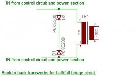
RC Snubbers are not recommended at 100khz at high voltage. In high frequency, high voltage, you better use ultrafast diode and transient voltage suppressor (transzorb/transil). You can try with BYV26C/E or UF4007 diode and P6KE200 or BZW06-188 transzorb. It will work much better than an RC snubber in high frequency, high voltage operation.
RC Snubbers are not recommended at 100khz at high voltage. In high frequency, high voltage, you better use ultrafast diode and transient voltage suppressor (transzorb/transil). You can try with BYV26C/E or UF4007 diode and P6KE200 or BZW06-188 transzorb. It will work much better than an RC snubber in high frequency, high voltage operation.

Hi Tahmid,
Are you sure that 209V acting TRANSIL will be good for damping of 30..50V overshots ?
Are you sure that 209V acting TRANSIL will be good for damping of 30..50V overshots ?
Hi Tolik,
30-50 overshots?
This circuit is to suppress transients over 200v even in the range of kilo volts and is to be connected across the primary of the transformer. If your design is half-bridge or full bridge, you should use 2 back to back transzorbs.
I do not quite understand why you are talking about 30-50v overshots as spikes here would be >200v. But if you need to suppress 30-50v spikes, P6KE30 and P6KE51 are available.
Since transients will be suppressed at the primary, no significant spikes would be produced at the output.
Attachments
- Status
- Not open for further replies.
- Home
- Amplifiers
- Power Supplies
- Building my first 12v smps...