Hi guys, as tittle said "Building BA-3 as analog output stage of noDac", well the noDac outputs 0,19Vrms so I was looking for something with a gain x10 to get near the standard 2Vrms, helping me to take the BA-3 option because I own original SK170BL, SJ74BL, K2013 & J313 from when I used Erno Borbely stuff, also it's not complicated to do it and adjust (very similar to Borbely), don't take to much room inside noDac box and is a lot of more easy and a lot of less money than make a DHT 4P1L with the same gain of course I don't expect the same SQ.
I read with attention NP BA-3 article, it seems with standard resistors values BA-3 fits nicely the x10 gain I'm looking for.
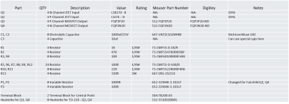
Attached NP BA-3 article to know if it's the latest or there is other new and also B.O.M. for a balanced unit that I will not do because all my system is SE.
I read Jfets have to be "matched if possible" at 10mA Idss, I have on hand:
SK170BL
9.48mA x 2
SJ74BL
9.02mA x 1
9.03mA x 1
or
10.11mA x 1
10.24mA x 1
What's best pair to use with the SK170BL?
I guess with these values P1 & P2 will remain 500R, right?
With the input voltage of +-25V can reach the x10 gain?
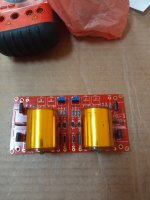
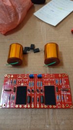
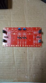
I will post pics of my work in progress.
TIA
Felipe
N.B. Big thanks to Jim aka 6L6 to give me a couple of PCB.
I read with attention NP BA-3 article, it seems with standard resistors values BA-3 fits nicely the x10 gain I'm looking for.
Attached NP BA-3 article to know if it's the latest or there is other new and also B.O.M. for a balanced unit that I will not do because all my system is SE.
I read Jfets have to be "matched if possible" at 10mA Idss, I have on hand:
SK170BL
9.48mA x 2
SJ74BL
9.02mA x 1
9.03mA x 1
or
10.11mA x 1
10.24mA x 1
What's best pair to use with the SK170BL?
I guess with these values P1 & P2 will remain 500R, right?
With the input voltage of +-25V can reach the x10 gain?
I will post pics of my work in progress.
TIA
Felipe
N.B. Big thanks to Jim aka 6L6 to give me a couple of PCB.
Attachments

You will be shocked at how good the BA-3 sounds. Might even replace the DHT stage.make a DHT 4P1L with the same gain of course I don't expect the same SQ.
They’re all a little away from the 2sk170, but P3 should help improve the match. You probably want some H2 anyway, so a little mismatch is okay.What's best pair to use with the SK170BL?
Yes, but going with 1k will give a little flexibility.I guess with these values P1 & P2 will remain 500R, right?
And yes, with +-25V, you can get 10X gain 0.19 Vrms input.
Have fun!
Thank you ra7.
So I will choose:
SK170BL
9.48mA x 2
SJ74BL
9.02mA x 1
9.03mA x 1
And use 1K pots for P1 & P2.
So I will choose:
SK170BL
9.48mA x 2
SJ74BL
9.02mA x 1
9.03mA x 1
And use 1K pots for P1 & P2.
Q3 is the P-channel device, so that would be the J313.
In the article, the bias is set to 50 mA for the output stage and approximately 8-10 mA for the input stage. I'd guess 60 mA is the total bias current.
In the article, the bias is set to 50 mA for the output stage and approximately 8-10 mA for the input stage. I'd guess 60 mA is the total bias current.
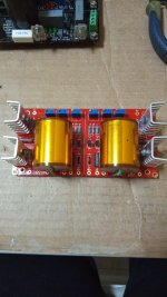
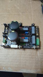
Thanks Ra7. I have to make a new order to Mouser because the electrolytics that I have are 50-63V so bigger diameter than PCB allows, four 1K trimmer and four heatsinks that also don't have in my stash. Attached pics with work in progress.
Attachments
Last edited:
Nice! Once you have the parts it can come together in an afternoon.
10 uF is plenty big. You can check the -3db point with the high pass filter calculator here:
https://www.digikey.com/en/resource...sion-calculator-low-pass-and-high-pass-filter
The R is the input impedance of the following stage. 10k is a good low value. Most things will have higher than 10k input impedance.
The 801A preamp have an input impedance of 150K so 0.53uF will be enough for 20Hz, I have on hand a couple of nice Auricaps 1uF 600V.
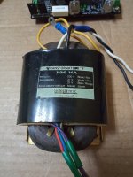
I have to decide what regulators I will use, I have on hand one +- regulator Salas BiB SSLV1.1 and a nice R-Core with dual secondary 21A 120VA so 60VA each secondary, the regs. have rectification & mains reservoir capacitor so be good to save space.
I have to decide what regulators I will use, I have on hand one +- regulator Salas BiB SSLV1.1 and a nice R-Core with dual secondary 21A 120VA so 60VA each secondary, the regs. have rectification & mains reservoir capacitor so be good to save space.
Last edited:
Listening the BA-3, could I bypass the 1K input resistor, I ask because the Vin it's too low circa 0,19Vrms so the resistor take off a lot of sound?
Some music sound weak and far.
1st stage Jfet only reach 6mA.
Some music sound weak and far.
1st stage Jfet only reach 6mA.
Last edited:
Also some music is masked and not heard or heard too little or blurred.
Let's see if it will sound better after the 3-4 hours of burning.
Let's see if it will sound better after the 3-4 hours of burning.
- Home
- Amplifiers
- Pass Labs
- Building BA-3 as analog output stage of noDac