Looks Great !
Couple Questions :
What are using for the Input Coupling Caps ?
You can add all the 1nf and 0.1uf caps you want but you still need to properly bypass inductance on the supply. You need 0603 0.1uf + 1210 2uf. We are dealing switching mosfets.
What Ferrite beads have you selected for the output filter ?

Dwight
Couple Questions :
What are using for the Input Coupling Caps ?
You can add all the 1nf and 0.1uf caps you want but you still need to properly bypass inductance on the supply. You need 0603 0.1uf + 1210 2uf. We are dealing switching mosfets.
What Ferrite beads have you selected for the output filter ?
Dwight
Looks Great !
Couple Questions :
What are using for the Input Coupling Caps ?
You can add all the 1nf and 0.1uf caps you want but you still need to properly bypass inductance on the supply. You need 0603 0.1uf + 1210 2uf. We are dealing switching mosfets.
What Ferrite beads have you selected for the output filter ?
Dwight
1/2uF 1210, that sorta thing, is a good idea for switchers yes. That's what I did on mine (along with an 0603 1nF &100nF).
Looks Great !
Couple Questions :
What are using for the Input Coupling Caps ?
1uF X7R 50V
Measured against WIMA MKP/FKP, no difference.
You can add all the 1nf and 0.1uf caps you want but you still need to properly bypass inductance on the supply. You need 0603 0.1uf + 1210 2uf. We are dealing switching mosfets.
Because why i need this and what do you mean by "inductance"? The actual decoupling (1n||100n) is done within <=2mm from the leads.
(And why do they need to be 0603/1210?)
Do you have any technical references (calculations, measurements, tests) about this?
Beside this, they aren't listed at the EVM nor in different datasheets from this TI family.
(Without knowing the boards power-path inductance, the information about 0603/1210 100n/2u renders useless to my knowledge. Additionally, the amp can be driven at different frequencies..)
What Ferrite beads have you selected for the output filter ?
2508051217Y6 (0805 6A Z=120R RDC=20mR)
ILHB1206ER121V (1206 6A Z=120R RDC=20mR)
Regards, doc
Last edited:
Well, i can't edit my last post anymore. I just read some posts back, where you stated that 1210 is within the same ESL as 0805.. This isnt true to my knowledge. 😵
Looking forward to your replies.
Regards, doc
Looking forward to your replies.
Regards, doc
http://www.avx.com/docs/techinfo/parasitc.pdf
you should also GOOGLE buck / stepdown converter design.
The TI reference design is geared for BOM aka lowest cost.
Look up the TAS5611/TAS5630 rederence design.
HOPEFULLY YOU FIND THIS INSIGHTFUL... 😀
Dwight
you should also GOOGLE buck / stepdown converter design.
The TI reference design is geared for BOM aka lowest cost.
Look up the TAS5611/TAS5630 rederence design.
HOPEFULLY YOU FIND THIS INSIGHTFUL... 😀
Dwight
Damn, it doesn't look like anyone stocks the NJU7181 and i can't figure out what to search for to get an alternative.
If it's still your concern I would be happy to swap one or two NJU7181 for an empty board when it's ready ;-). NJU7181 is a sweet chip, simple and hardly to be replaced. There is a complicated alternative via a microprocessor though...
Mike
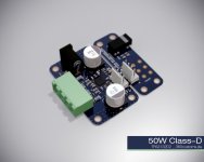
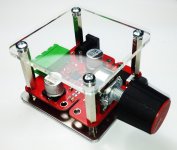
Running nice and "dead quiet" at 400 - 1000kHz. 🙂
http://www.diyaudio.com/forums/class-d/87913-class-d-amp-photo-gallery-94.html#post4179209
http://www.diyaudio.com/forums/class-d/87913-class-d-amp-photo-gallery-94.html#post4179209
Attachments
Last edited:
More square caps have lower ESL than "longer" ones, in fact reverse geometry capacitors exist with the connections on the longer edges to reduce ESL.
It's not so much the capacitor, but more how it changes the PCB layout that reduces the ESL with a wider capacitor, as I understand it anyway. Not hugely necessary on one of these amps but nice to have...
Doc, I noticed you're using a number of 0402s? No reason why not, but it looks like 0603s would fit nicely.
Dunno, maybe because i do everything in 0402/0201 at work.
We did some more tests with the result of having a solid 50W continuous output power with free air cooling at 2x8R.
Tested at PVCC:23V5, Iin:2.2A, 30Hz sine wave, 30 minutes.
Temps were:
tamb:18°C
tpcb_bottom: 95°C
tcapacitor_bulk: 56°C
tic_top: 142°C
Noone will ever run pure 30Hz for more than a couple of seconds i guess. 😀
Peak power is higher of course.
Considering 23,5V*2,2A input this is 50W total output power, i.e. 2x25W. Otherwise this would be over-unity😉
yes efficiency seems very high even with 25W here, so one value probably not accurate. I have no idea about temperatures/heat dissipation, but would 1.7W loss that needs dissipation get temperatures this high? It is a really small amplifier pcb and chip, so that influences temperature I guess.
look at http://www.ti.com/lit/ds/slos841b/slos841b.pdf, fig 34 shows a thermal plot. This might give you an idea.
Theres a bit of calculation going on at:
http://www.diyaudio.com/forums/class-d/251859-building-tpa3132-amp-board-3.html#post3844323
http://www.diyaudio.com/forums/class-d/251859-building-tpa3132-amp-board-3.html#post3844405
So lets see:
Ideal:
TPA3132 = 8R/(8R+0R12+0R12) = 0.97 = 97%
TA = 18°C
Pout = 50W
Efficiency: 👎 = 97%
Rth_JA = 31K/W
Pdiss = (50W / 0.97) - 50W = 1.54W
TC = TA + Pdiss * Rth_JA = 18°C + 1.54W * 31K/W = 66°C
Well, we wont have that 97% in practice, so lets assume 92%:
Pdiss = (50W / 0.92) - 50W = 4.34W
TC = TA + Pdiss * Rth_JA = 18°C + 4.34W * 31K/W = 152.54°C
For 140°C:
Pout(TC)=[n*(TC-TA)] / [Rth_JA - Rth_JA*n]
Pout(140°C) = [0.92*(140°C-18°C)] / [31K/W - 31K/W*0.92] = 45.25W
So having the correct values from the test:
VCC:23.5V
Iin:2.2A
n=0.92%
Pout: 23V5*2.2A*0.92 = 47.56W
There you have it.
Note:
Regardless of a heatsink or not, this is the maximum continuous output power at Tamb=18°C. You wont get any higher, except you lower Tamb or use forced cooling. Peak power will be higher and, thanks to the thermal capacitance of a heatsink, the duration for peak power is higher with bigger heatsink, but you need to take in account, that this capacitance "discharges" slowly, so your "burst" ratio will get smaller as more often you do that. (literaly) To "discharge" it, forced air cooling the way to go.
I made a short vid of the "test:
https://www.youtube.com/watch?v=riYs_1FeYLo
Last edited:
Additional "Anti-Pop":
TPA3132D2 - delay and scram (anti-POP) - also for TPA3116 / TPA3118 - # 360customs
TPA3132D2 - delay and scram (anti-POP) - also for TPA3116 / TPA3118 - # 360customs
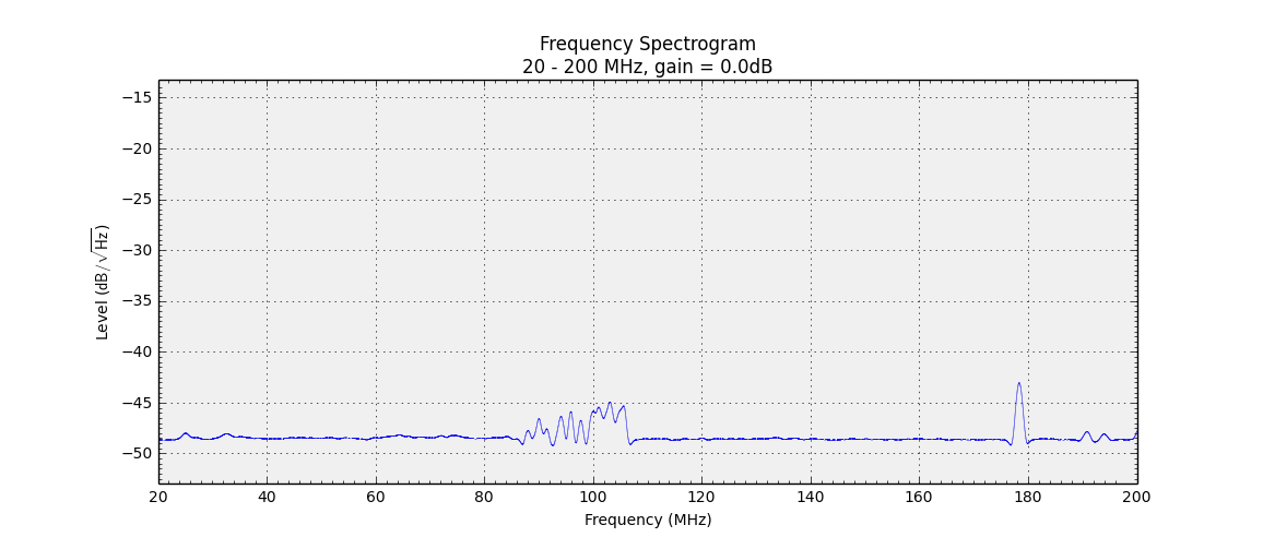
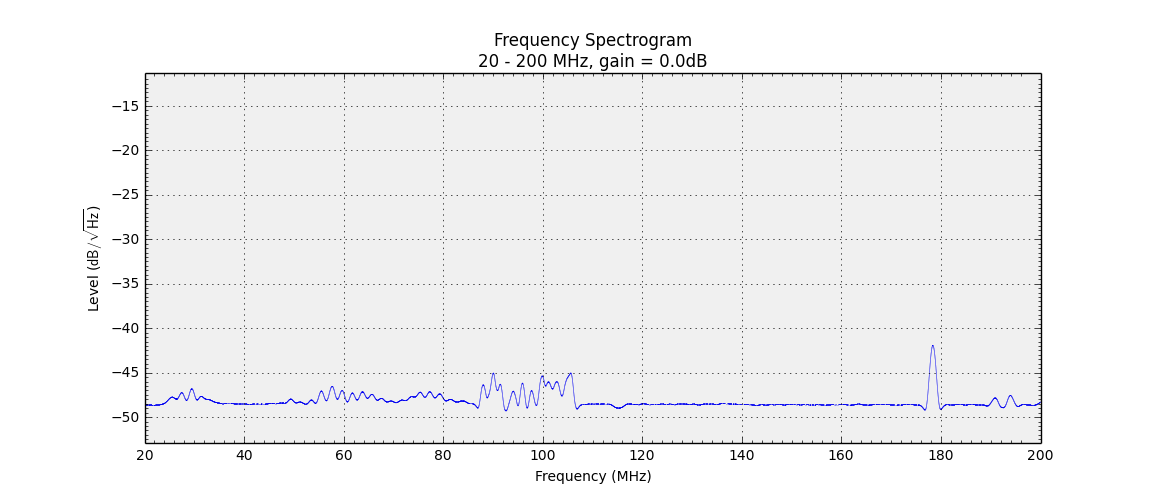
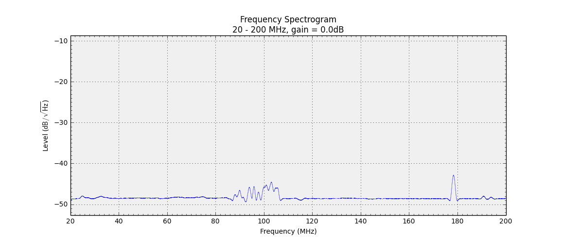
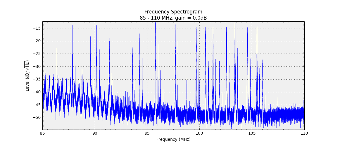
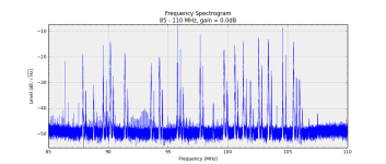
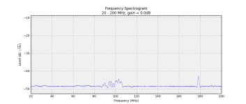
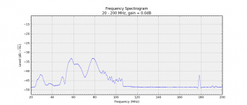
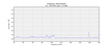
Comparing the MAX9709 and TPA3132D2 in filterless configuration:
1 channel loaded 8R 150cm cable
50cm distance from antenna (70cm cable)
Antenna <-50cm-> Amp <- 150cm -> Speaker
Idle:
MAX9709:
TPA3132D2:

MAX9709 with no speaker connected:
TPA3132D2 with no speaker connected:
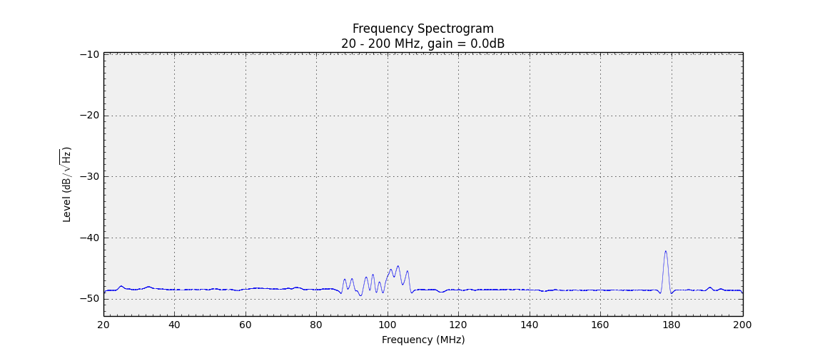
Idle FM-range detail:
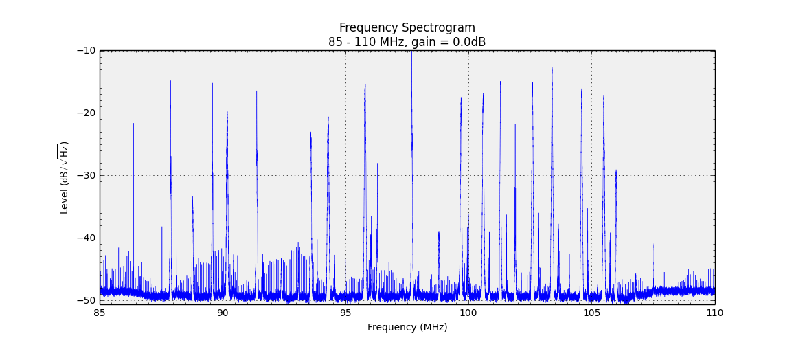
MAX9709 FM-range detail:
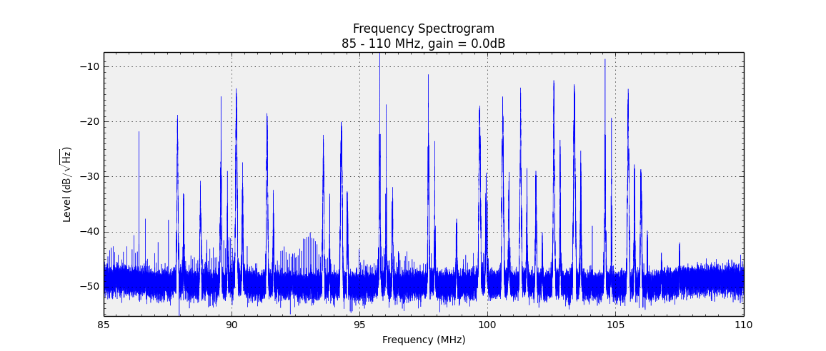
TPA3132D2 FM-range detail:
1 channel loaded 8R 150cm cable
50cm distance from antenna (70cm cable)
Antenna <-50cm-> Amp <- 150cm -> Speaker
Idle:
MAX9709:
TPA3132D2:
MAX9709 with no speaker connected:
TPA3132D2 with no speaker connected:
Idle FM-range detail:
MAX9709 FM-range detail:
TPA3132D2 FM-range detail:
Attachments
-
 max_85_110_16ms_4096_MAX.png94.3 KB · Views: 242
 -
 idle_85_110_16ms_4096_MAX.png95.5 KB · Views: 248
 -
 tpa_without_load.png36.4 KB · Views: 242
 -
 max_without_load.png36 KB · Views: 245
 -
 tpa.png42.3 KB · Views: 242
 -
 max.png39.5 KB · Views: 242
 -
 idle.png38.4 KB · Views: 252
 -
 tpa_85_110_16ms_4096_MAX.png106.2 KB · Views: 240
- Status
- Not open for further replies.
- Home
- Amplifiers
- Class D
- Building a TPA3132 amp board