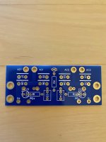
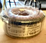
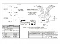
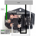
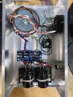
I am just about ready to power up and test my PSU. Before I do that, I want to run through some of the connection to make sure I have them right. I am using the same Peter Daniel board that 6L6 used (as shown in the photos in post # 1 of this thread). I have attached a photo of the empty board. I am using a Hammond 1182J22 transformer (photo and technical sheet attached). I am using two 50v 10,000uf caps (https://www.mouser.com/ProductDetail/647-LKS1H103MESB) for C1 and C2. I am not mounting them directly to the Board. Instead, I am running leads from the C1 and C2 holes on the board to the caps. Per the input from Ben Mah above in post # 2991, the black and brown primaries from the transformer are wired to the "hot" pole on the "on" end of the switch, and the white and orange to the "neutral" pole (the wiring diagram for the switch is attached). I have a resistor installed on the board for an LED, but have not added the LED yet.
Here are the connections I want to check:
1) Red and blue secondaries from the transformer to the two AC1 holes on the board. Correct? Does it matter which one goes in which hole?
2) Gray and yellow secondaries form the transformer to the two AC2 holes on the board. Correct? Does it matter which one goes in which hole?
3) Leads from the "+" holes for C1 and C2 on the board (the two outside holes, with "C1" and "C2" printed right next to them) to the positive terminal on each of the 50v 10,000uf caps.
4) Leads from the negative holes for C1 and C2 on the board (the two inside holes) to the negative terminal on each of the 50v 10,000uf caps.
5) VG+ on the board to the hot pin on the umbilical jack.
6) PG+ on the board to the ground pin on the umbilical jack.
7) VG- on the board to the neutral pin on the umbilical jack.
8) PG- on the board to the "-" post on the bridge rectifier.
9) Two .22uf film caps mounted as shown in 6L6's photos in post # 1 (one side in the holes next to "R1" and "R2" on the board, and the other side in the holes just below the C1 and C2 "+" holes).
I have attached a photo of the full PSU, so please let me know as well if you see any other issues. Thank you for checking my work.
Attachments
Wiring of the rectifier board to capacitors and the orientation of the rectifiers do not look correct. The board looks similar to 6L6's but it is not identical. Things appear to have been reversed.
I have marked up the correct wiring for the capacitors.

I have marked up the correct wiring for the capacitors.
You should build and test in stages. For the first stage install the rectifier diodes and connect the transformer to the board, but no capacitors. Power up, preferably with a Dim Bulb Tester attached, and with you meter set to VDC, red probe on V+ and black probe on PG+, the reading should be a positive voltage. Then red probe on PG- and black probe on V-, again it should be a positive voltage. If successful, then continue to connect capacitors. Then test again with Dim Bulb Tester attached. Black probe to Gnd, red probe to V+ should show positive voltage and red probe to V- should show negative voltage. Discharge capacitors with a resistor after powering off.
Excellent! Thanks so much!
Re the ground line from the capacitors shown in your diagram, am I correct that it runs to the ground pin on the umbilical plug, and to the "-" pole on the bridge rectifier?
Re the ground line from the capacitors shown in your diagram, am I correct that it runs to the ground pin on the umbilical plug, and to the "-" pole on the bridge rectifier?
BTW, I should have noticed the rectifier orientation. So focused on the photos online that I missed the markings on the board right in front of me. Lesson learned.

I made the adjustments identified by Ben Mah. I tested after re-installing the rectifier diodes. The voltage was +/- 22.8. I added the capacitors then tested again. The voltage is +/- 35.2. Per the build guide, the desirable range is 28-34v. So, mine is a bit high. Is it acceptable, or do I need to adjust it down? If the latter, what is the recommended approach for lowering it?
Just out of interest, what does the voltage out of the wall measure? 120VAC is "nominal".
At the house I'm in right now it measures 123.5VAC.
The specs are specified at 117 or so VAC I think. The regulation of the transformer is a factor too. Under load the voltages drop a bit.
I don't expect your 35VDC is a problem.
At the house I'm in right now it measures 123.5VAC.
The specs are specified at 117 or so VAC I think. The regulation of the transformer is a factor too. Under load the voltages drop a bit.
I don't expect your 35VDC is a problem.
The PS voltage out will be high with no load. As mhenschel said, the voltage will drop under load, and should not be a problem.
Hi Eric,As mjf pointed out, double check all of your power supply wire voltages. It's harder to visually inspect your images because you've used the same wires for signal as for power supply. Double check the output of the voltage regulators on the PCB. Use the parallel resistors (R3 & R4) and (R31 & R33) as test points with reference to ground to make sure you are getting +/- 24v out of your regulators on each board.
Presuming your power supply is wired correctly, the next thing to explore is Q2 - they are VERY static sensitive and a number of people blow them before their first power up. Double check your small transistors (especially Q4, Q5, Q10, Q11 to make sure you go the orientation correct.
I need to check if my PS is made correctly, for me the + / - rail and ground is a new concept not at all familiar with.
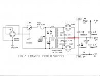
In the schematic attached I have 64V between 1 and 2 (1 near to +30 and 2 near to -30) and 32V between 1 and 3,4 (near GND) and between 2 and 3,4 (near GND).
I connected 1 to the +DC IN pad from the preamp PCB; 2 to the -DC IN pad from the preamp PCB and 3,4 to the PAD 2 GROUND pad from the preamp PCB.
Between the PAD 2 GROUND on the preamp PCB and R3 / R33 I had 23.9V on both boards when I checked a few weeks ago.
This morning I connected everything to check step by step all the connections. While measuring after a while I noticed that at one of the boards the red LED was not working anymore. I measured 23.9V between R3 and PAD 2 GROUND but no voltage between R33 and PAD 2 GROUND.
At the other board with LED working I still had 23.9V between R3 / R33 and PAD 2 GROUND. I put my finger at that working board on the R33 corresponding regulator and it was very hot. The other regulator it was not even warm.
I unplugged everything.
Please help me debug, I am stuck.
Attachments
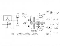
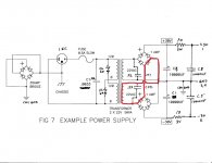
Your power supply schematic looks wrong. One of the transformer secondaries is shorted, which I have shown in the first attachment. The second attached schematic shows the correct wiring. Your power supply wiring needs to be corrected before proceeding further.
Attachments
Ben: Isn't your "short" condition the same for both secondaries?
I'm just guessing, but I think the benefit of having two bridges is obviated by the "centre tapped" wiring that has been implemented. Better to follow 6L6's diagram at the beginning of the thread.
I'm curious how jackinnj's advice for the inrush limiter got translated into what's shown. I'd have thought one unit right after the fuse was correct. Or one before each primary following the fuse. Maybe it's an issue of physical wiring?
The subject difficulty seems to be at the on-board regulators; a short, bad solder joint, or a solder bridge... ? Photos might help show what's going on.
I don't see a short in the other secondary. But combining a centre tap with dual bridge rectifiers is not necessary and looks wrong to me, and it should be rectified. 🙂
The implementation of the thermistors looks correct. The typical First Watt power supply is like that. However only one thermistor will probably work but it will carry twice the current and heat up faster. That would probably not be an issue with the low current demand of the preamp. I usually only use thermistors in power amplifiers though. The current draw of a preamp is low compared to a Class A amplifier.
Yes, photos of the power supply would be useful.
Pun appreciated.
I imagine the thermistors are attractive because of all that capacitance that needs charging, not the running currents?
I'm not at all confident that the drawing reflects the implementation, hence the suggestion for film. The outputs of the unattached raw supply seem to be correct -- +/-30 some odd volts. It's when those supplies are connected to the regulators that the mischief is occurring, no? Detailed photos of both sides of the boards at the regulators would be most helpful I think.
My understanding of inrush current is that yes, the capacitance needs charging but the power transformer, if low VA as used in preamps, will also have a low maximum current.
Thanks for all the replies and help. Sorry, the schematic attached was one that I found here in this forum, to help me explain better the PS voltages. I have attached:
Can I eliminate the PS? Do you need more pics / info from the PS?
Depending your replies I will start adding pics of the preamp board in the regulators area.
Thanks!
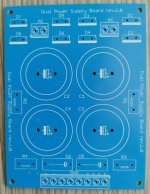
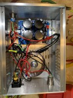
- pictures of the actual bord I have used for the PS build
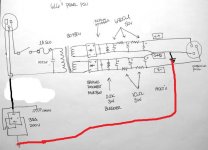
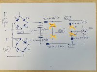
- schematic that I have drawn myself based on the board - I hope that it follows the board layout, I am not that skilled
- in the schematic based on the advice from here I have installed also the red crossed capacitors next to C1 and C2 - in total 4 pcs 10.000 uF @ 50V
- also instead of the red crossed capacitors C5 and C6 I have installed LED's.
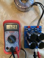
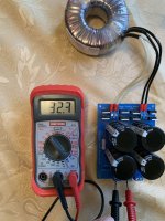
- between V- and GND and also between V+ and GND I measure 32.3V - please see attached.
- between V- and V+ I measure 64.8 V
- Iast pic is of the finished PS
Can I eliminate the PS? Do you need more pics / info from the PS?
Depending your replies I will start adding pics of the preamp board in the regulators area.
Thanks!
Attachments

Your measured values look ok. The R3/R4 bleeder values (1K across the rails) are lower than I would use (so you're burning a fair bit of current) but that would not be the cause of your problem.
- Home
- Amplifiers
- Pass Labs
- Building a Pearl 2