Adrculda said:
Ohh well...
4 pairs in my living room will be fine by me...
Just need to work on this amp and see how it handles them.
yeah - in your living room would be just fine. Not sure I'd want to gig with them.
wg_ski said:
yeah - in your living room would be just fine. Not sure I'd want to gig with them.
Im trying to stay away from too large venues now...
besides 8 cabinets loaded with 2 x 15" subs PLUS your forgetting the 4 x 18" folded horns i have !!!
with the proper crossover and the right amplification this is plenty for a 70,000 sqft hall and then some !!
The main problem you will run into with using those cabinets in a live non-home audio application is the mid and high frequencies. The waveguide looks to be quite exponential. They won't have much throw to them as they are designed to be near-field cabinets. A crowd absorbs high frequencies very effectively, so you'll end up losing much of it before the back of the room.
imix500 said:The main problem you will run into with using those cabinets in a live non-home audio application is the mid and high frequencies. The waveguide looks to be quite exponential. They won't have much throw to them as they are designed to be near-field cabinets. A crowd absorbs high frequencies very effectively, so you'll end up losing much of it before the back of the room.
the max crowd that im aiming for right now is not to exceed 200PPL
i think those 8 cabinets will do fine if i have to i might just build some extra insurance with some serious bullet power or again a massive 2" compression horn on each side should do the trick.
wg_ski said:Those look like an updated version of the old HED's. We used to blow those out on a regular basis - even with a Flame Linear. The suspensions just couldn't take the pounding and the spiders get separated too easily. Hate to think what a CS800 or Dirty Harry would do to them.
To be accurate, the models that i had sold was the VS-15, during 1995 if i remember well. And i did this to help an old friend which had got the agency of Cerwin Vega in Greece during this time.
Your remarks are by some way similar to mine regarding these loudspeakers. My tactics was to install them in 2 pairs in small clubs of 100 peoples as much, and to drive them (what a coincidence with what you said! 🙁 ) with CS-800. I had enough ripped woofer's suspensions after 1 year of use! And no replacement cones! The only choice for repairing was the replace of the woofer... which was very expensive.
Oh my! what a nightmare with the complaints of my customers!
Why you remember me these old bad moments
 ... bad wg_ski
  ?
? Regs
Fotios
If I blow the woofers to kingdom come then ...
time to upgrade to a woofer that can handle more power....
If i dip my fingers into the car audio or the high end audio market i will be WAY more than these puppies can do.
Besides i heard from a lot of PPL that the CV has 2 or 3 versions of this 15" woofer and from what i heard they are using the weaker ones due to amplifier size needed to drive 2 of those monsters, which wont be a big problem for me 😛
But at this point...
the way i have to build the amp(s) to drive the CLS215 has shifted.
for sure i want to bi-amp them due to better sonic performance and less stress on the speakers and crossovers.
i need to get those boards with the drivers going ASAP!!!
Fotios...
what wattage were the resistors you used on the output of your transistors ?
and unlike most of the people on this board i will pull the drivers on a separate board on the heat sink.
This allows me to put the driver board closer to the cap banks and keep wire lengths to a minimum.
Attachments
and unlike most of the people on this board i will pull the drivers on a separate board on the heat sink.
This allows me to put the driver board closer to the cap banks and keep wire lengths to a minimum.
I believe it's better to have the driver transistors near the output transistors than near the supply. Inductance in series with the output stage bases (which transforms into negative resistance seen from the emitters at HF) seems to be what causes problems with capacitive loads.
Having the whole output stage near the power supply is a pretty good idea though 🙂
megajocke said:
I believe it's better to have the driver transistors near the output transistors than near the supply. Inductance in series with the output stage bases (which transforms into negative resistance seen from the emitters at HF) seems to be what causes problems with capacitive loads.
Having the whole output stage near the power supply is a pretty good idea though 🙂
You do what you can - but such is the problem with scaling these amps up - they become their own stabilty problems and each implementation needs to be worked out individually. What used to work doesn't. And why you'll never get "audiophile" quality - it becomes more and more impossible to follow all of Self (and others') rules for proper layout when thing simply can't be connected at single points anymore. And you've got to back off on the amount of feedback (loop gain) because of those parasitics like distributed inductance in the base leads and bias lines. Distortion can be made reasonable, but you reach a point where it just won't go lower and doesn't need to be anyway.
megajocke said:
I believe it's better to have the driver transistors near the output transistors than near the supply. Inductance in series with the output stage bases (which transforms into negative resistance seen from the emitters at HF) seems to be what causes problems with capacitive loads.
Having the whole output stage near the power supply is a pretty good idea though 🙂
Sorry what i mean to say that the driver and output transistors will be on a separate board on the heat sink, allowing me to double up if i need to.
I will call this the output board.
the way i want to set it up is that if i would like to i can series 2 boards or more if i need more power 😉
there will be provisions for power and signal input on both ends of the board.
wg_ski said:
You do what you can - but such is the problem with scaling these amps up - they become their own stabilty problems and each implementation needs to be worked out individually. What used to work doesn't. And why you'll never get "audiophile" quality - it becomes more and more impossible to follow all of Self (and others') rules for proper layout when thing simply can't be connected at single points anymore. And you've got to back off on the amount of feedback (loop gain) because of those parasitics like distributed inductance in the base leads and bias lines. Distortion can be made reasonable, but you reach a point where it just won't go lower and doesn't need to be anyway.
So what your saying is drop the feedback circuit ...
OK
no biggie..
what software is there for simulating circuits in real time on the computer ??
also what software are you guys using to draw the schematics and setup the PCB's ??
Adrculda said:
So what your saying is drop the feedback circuit ...
OK
no biggie..
what software is there for simulating circuits in real time on the computer ??
also what software are you guys using to draw the schematics and setup the PCB's ??
Oh yeah, you're ready...
😱
MJL21193 said:
Oh yeah, you're ready...
😱
ok ..
its been about 7 years since i dealt with this stuff.. i forgot most of this **** plus it was car audio.
besides...
last i was working on something it wasn't dealing with no where near the voltages and as many output devices.
Also been thinking about an auto biasing option through the NJL1302/3281 transistors...
No problem.
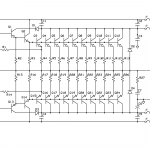
Here's one that actually works:

It's stable and maintains a steady idle current. To increase power, ramp up the voltage and add more outputs.
Here's one that actually works:
It's stable and maintains a steady idle current. To increase power, ramp up the voltage and add more outputs.
Adrculda said:i need to get those boards with the drivers going ASAP!!!
Fotios...
what wattage were the resistors you used on the output of your transistors ?
I use as emiter resistors 0,33Ù/10W. Also, in Zobel four parallel/series connected resistors of 10Ù/5W each (like Peavey) because in high power output stages only one resistor of 5W in Zobel can be burned very easy, and has no audible effect so you can't perceive it... the only way for this it is when the output transistors starts to burned out... 😀
As for the software that i use, it is a complette suite including except schematic, layout and fabrication manager also a spice simulator, an electromagnetic and a thermal analyzer. It is the EDWin XP of Visionics. Of course, there are better softwares like the Altium design center (previous Protel) and the top Orcad, but they are most complex from the enough complex EDWin that i am using.
This circuit presented by MJL21193, it seems very good and enough simple for such type works like your. Of course, MJL can offers to you ready the layouts of pcbs and the rest, because he is a very polite man. Thus, there is no reason to you draw and implement this circuit of ESP (as you said you are very hasty) consequently you don't have the need for a CAD-CAE software at this moment. Leave this option for later, now you must be looking to finish your work "ASAP".
Regs
Fotios
Regs
Fotios
MJL21193 said:No problem.
Here's one that actually works:
It's stable and maintains a steady idle current. To increase power, ramp up the voltage and add more outputs.
fotios said:
I use as emiter resistors 0,33Ù/10W. Also, in Zobel four parallel/series connected resistors of 10Ù/5W each (like Peavey) because in high power output stages only one resistor of 5W in Zobel can be burned very easy, and has no audible effect so you can't perceive it... the only way for this it is when the output transistors starts to burned out... 😀
As for the software that i use, it is a complette suite including except schematic, layout and fabrication manager also a spice simulator, an electromagnetic and a thermal analyzer. It is the EDWin XP of Visionics. Of course, there are better softwares like the Altium design center (previous Protel) and the top Orcad, but they are most complex from the enough complex EDWin that i am using.
This circuit presented by MJL21193, it seems very good and enough simple for such type works like your. Of course, MJL can offers to you ready the layouts of pcbs and the rest, because he is a very polite man. Thus, there is no reason to you draw and implement this circuit of ESP (as you said you are very hasty) consequently you don't have the need for a CAD-CAE software at this moment. Leave this option for later, now you must be looking to finish your work "ASAP".
Regs
Fotios
Regs
Fotios
Thanks all...
i had a busy 2 days here at home, but i have Orcad and Altium Design Center on their way... from a "Friend" 😉
this way i can have the boards laid out the way i want them not how my PCB guy sees fit...
fotios said:Of course, MJL can offers to you ready the layouts of pcbs and the rest, because he is a very polite man.
As a matter of fact... 😉
Adrculda said:
i have Orcad and Altium Design Center on their way... from a "Friend" 😉
this way i can have the boards laid out the way i want them not how my PCB guy sees fit...
Good luck and have fun with it.
🙂
Attachments
MJL21193 said:
As a matter of fact... 😉
Good luck and have fun with it.
🙂
Hehehe...
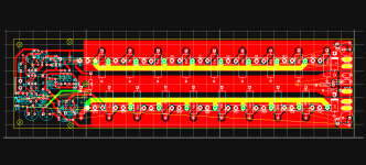
Ready food! And well cooked... mmm... pcb drawing seems to be ready for a cooling aggregate driven by a 120 X 120 mm axial fan.
Get it and eat it!
Fotios
MJL21193 said:No problem.
Here's one that actually works:
It's stable and maintains a steady idle current. To increase power, ramp up the voltage and add more outputs.
Hey, MJL21193 you are keeping secret your protection computer.
Never mind 😀 I do the same like you. 😉
Regs
Fotios

NO kidding...
talk about being served on the platter 😛
Now ...
Can i get a side order of BOM ??

Also what voltage did you design this circuit in mind with ??
i might just want to add one more output transistor on each side as i like round numbers.
And whats the guestimate output on this toy 😛
To be accurate, the only that i consider is missing from this circuit, it is a current mirror (not for the usual B.S. writen from members but for eliminating the DC offset in output, unless you must match the LTP transistors. A trim pot can balance the collector currents of LTP as well. Please MJL give instructions to Ardculda, this is your duty.
The second that is missing is a VI limitter for protecting output transistors from reactive loading. Also this, is very common and easy to implement.
These all are tasks regarding MJL and not me.
Don't worry Ardculda, MJL is a brave man ready to offer his service in everyone that needs it. It is a knight ready to kill the dragon with his amplifier spear.
Regs
Fotios
fotios said:
Of course, there are better softwares like the Altium design center (previous Protel) and the top Orcad, but they are most complex from the enough complex EDWin that i am using.
You are a bit right...
looked for EDWin didnt have too much luck, but found OrCAD V16 and Altium Designer Suite V6.6 REALLY FAST !!
i have 2 versions of OrCAD one is the Full version and the other is the "Portable" version.
opened up the portable version and is a million times more advanced than that PCBExpres crap i was forced to work in 😱
Love it though... waiting for the full version to finish downloading !
The only that i consider is missing from this circuit, it is a current mirror (not for the usual B.S. writen from members but for eliminating the DC offset in output, unless you must match the LTP transistors. A trim pot can balance the collector currents of LTP as well. Please MJL give instructions to Ardculda, this is your duty.
The second that is missing is a VI limitter for protecting output transistors from reactive loading. Also this, is very common and easy to implement. [/B]
Doesnt seem like a problem since i want to add another pair of output transistors and at the same time we can implement those circuits.
well have to if i want to add that...
EDITED - spelling and poor grammar :S
- Status
- Not open for further replies.
- Home
- Amplifiers
- Solid State
- Building a Monster... Class A