I'm building a high-ish current series regulator that, like many, requires a CCS between the unregulated supply and base of the pass transistor. To keep dissipation low, it's in my best interest to keep a low voltage drop across the pass transistor, which leaves little room for the CCS to operate. It's easy to make a great, high bandwidth CCS that drops 10V, but MOSFET cascodes are off the table when we only have 2-3V to work with.
My first stop was @Mark Johnson 's excellent thread on measuring transistors' Early voltage and saturation characteristics, and Gary Pimm's articles on measuring CCS performance. I tried to recreate Pimm's rig using an AP, and test some bits of sand I had lying around. I was particularly interested in seeing how bad the MJE340's capacitance would be, considering the high Early voltage would make for an otherwise excellent CCS.
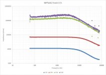
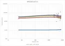
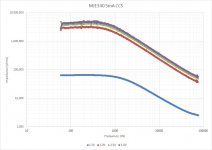
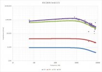
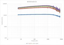
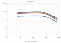
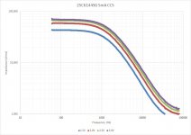
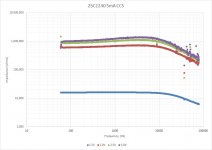
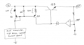
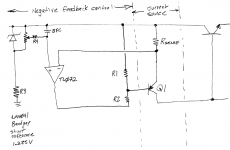
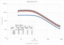
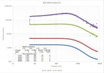
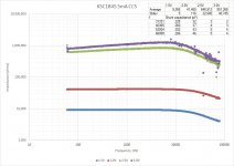
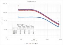
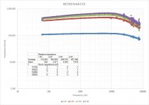
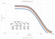
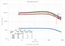
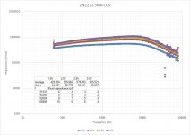
Here's what the test rig looked like. The supply is a well filtered Mean Well 48V switcher. I inserted a Vbe multiplier with a large bypass cap between the bottom of the sense resistor and ground to allow for easy trimming of the voltage across the CCS being tested, and stepped the voltage from the collector to the bottom of the emitter resistor to 1.5V, 2.0V, 2.5V, and 3V. Here are the results. The analyzer/generator is an APx515.

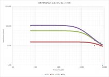
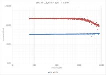
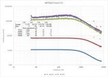
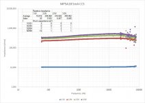
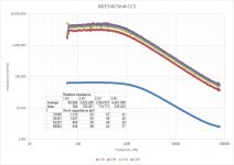
The data is attached. Sweeps were run from 60Hz to 80kHz. The low frequency limit was set to avoid cap charging issues, and avoid any issues with 60Hz noise coupling to the circuit. The test signal is 100mVRMS (i.e. a considerable portion of Vce!). When reading the 1.5V lines, do consider that the reference voltage of 1.8V will exceed Vce, but interestingly most devices continue to do their thing, and some do it better than others. Also note that the Y axis changes from graph to graph.
The 250R degeneration resistor is evening things out, but there's still some significant spread between the different parts. I was hopeful for the 2SC6144SG, but the high capacitance won it the title of biggest loser.
I'll need to pick up some ZTX parts to try, and would like to see how little voltage I need to get away with a cascode using Si diodes for bias. Perhaps some logic-level MOSFETs could work, too, if anyone has suggestions.
I'm also struggling to calculate the shunt capacitance-- could anyone point me in the right direction?
My first stop was @Mark Johnson 's excellent thread on measuring transistors' Early voltage and saturation characteristics, and Gary Pimm's articles on measuring CCS performance. I tried to recreate Pimm's rig using an AP, and test some bits of sand I had lying around. I was particularly interested in seeing how bad the MJE340's capacitance would be, considering the high Early voltage would make for an otherwise excellent CCS.
Here's what the test rig looked like. The supply is a well filtered Mean Well 48V switcher. I inserted a Vbe multiplier with a large bypass cap between the bottom of the sense resistor and ground to allow for easy trimming of the voltage across the CCS being tested, and stepped the voltage from the collector to the bottom of the emitter resistor to 1.5V, 2.0V, 2.5V, and 3V. Here are the results. The analyzer/generator is an APx515.
The data is attached. Sweeps were run from 60Hz to 80kHz. The low frequency limit was set to avoid cap charging issues, and avoid any issues with 60Hz noise coupling to the circuit. The test signal is 100mVRMS (i.e. a considerable portion of Vce!). When reading the 1.5V lines, do consider that the reference voltage of 1.8V will exceed Vce, but interestingly most devices continue to do their thing, and some do it better than others. Also note that the Y axis changes from graph to graph.
The 250R degeneration resistor is evening things out, but there's still some significant spread between the different parts. I was hopeful for the 2SC6144SG, but the high capacitance won it the title of biggest loser.
I'll need to pick up some ZTX parts to try, and would like to see how little voltage I need to get away with a cascode using Si diodes for bias. Perhaps some logic-level MOSFETs could work, too, if anyone has suggestions.
I'm also struggling to calculate the shunt capacitance-- could anyone point me in the right direction?
Attachments
LM334
5mA right in its sweet spot, 1v guaranteed maximum Vdiff required at that. In fact its closer to 0.8v. Oh, and 40Vdiff tolerance.
Also - cheap!
5mA right in its sweet spot, 1v guaranteed maximum Vdiff required at that. In fact its closer to 0.8v. Oh, and 40Vdiff tolerance.
Also - cheap!
Try BSS139 cascodes ,it can work with 2.5V voltage drop, max ~30mA. I use them for the same purpose in the 4A regulators for my Le Monstre amp.I'm building a high-ish current series regulator that, like many, requires a CCS between the unregulated supply and base of the pass transistor. To keep dissipation low, it's in my best interest to keep a low voltage drop across the pass transistor, which leaves little room for the CCS to operate. It's easy to make a great, high bandwidth CCS that drops 10V, but MOSFET cascodes are off the table when we only have 2-3V to work with.
I'm also struggling to calculate the shunt capacitance-- could anyone point me in the right direction? /QUOTE said:I have no suggestions re calculating shunt capacitance. But if you're trying to measure/estimate effective shunt C, you might try shunting the output with an experimentally selected cap that reduces signal response at higher frequencies by 50%. The empirical value should be comparable to the circuit's shunt C.
Can you provide some details about measurement instrumentation? It would seem that the 4K resistor (in series with the Vbe multiplier) in parallel with the AP input impedance (100K) of would limit the measured resistance to less than 4K. Interesting!
Thanks all for the helpful responses. 🙂
If I'm only 7 years behind, that's better than average for me. 🙂 I'm not sure I understand how this works-- are we not basically passing the buck to the current mirror? Or to ask the question differently, how is this better than using an elaborate CCS to bias a ~1V reference, which in turn biases a PNP?
I was hoping this would be it! Alas, it is not. Attached some measurements, since we're operating in the knee of the curve, the dynamic impedance drops rapidly. It's not the worst, but for the same voltage drop we could get 2-5x better with the right BJT.
I'll pick some up, thanks for the suggestion. I do have some BSS126, but need to make an adapter to throw SMD parts into the test rig. Maybe this weekend.
This would work, but would need some high precision low value capacitors, or perhaps a variable cap with a calibrated capacitance meter. I have neither. 🙂
I think the algebra works out to something like this.
Vin/Vout = (Rsense) / (Rsense + Zccs)
1/Zccs = 1/Rccs + 1/XCshunt = 1/Rccs + 2*pi*f*Cshunt
Where Zccs is the total CCS impedance, Rccs is the CCS's low frequency impedance, and Cshunt is the CCS shunt capacitance, Zccs is the measured CCS impedance and XCshunt is the capacitive reactance of the CCS at a frequency of f. Forgive the variable soup and all the Cs.
Which works out to:
Cccs = (Rccs - Zccs) / (2 * pi * f * Rccs * Zccs)
Way out to lunch? This gets me around 12pF for the LM334, which is close to the datasheet value, I'm measuring closer to 150pF for the DN2540. Gary Pimm simply uses Cshunt = 1/(2 * pi * f * Z), which is true for the above when Rccs >>> XCshunt... but he gets just 32pF for the DN2540. Perhaps channel length modulation, as he tests at 9V?
The trick is to look at is as a voltage divider, where the CCS is the upper leg, and the 4k resistor is the lower leg. The generator injects a signal to the top of the divider, and the voltage is measured across the 4k sense resistor (in parallel with the AP's 100k // ~250pF loading), with the assumption that the Vbe multiplier's impedance is zero across the sampled frequency range. The CCS impedance is then computed as:
Zccs = 4k * Vin / Vout - 4k
4k was chosen as it was big enough to generate an easily measurable voltage, but small enough to not drop an excessive DC voltage or create a pole with the analyzer's internal capacitance within the measurement range (which defines a pole around 150kHz). At some point, I'll need to add a preamp. 🙂
I tested a few more parts, including the venerable DN2540. I'll retest it at higher voltages as my result is so far off from Pimm's that something must be amiss.
Facing a similar problem in 2015, I used a fancy and elaborate current source to get high impedance, plus a moderately-degenerated current mirror to get low dropout.
If I'm only 7 years behind, that's better than average for me. 🙂 I'm not sure I understand how this works-- are we not basically passing the buck to the current mirror? Or to ask the question differently, how is this better than using an elaborate CCS to bias a ~1V reference, which in turn biases a PNP?
LM334
I was hoping this would be it! Alas, it is not. Attached some measurements, since we're operating in the knee of the curve, the dynamic impedance drops rapidly. It's not the worst, but for the same voltage drop we could get 2-5x better with the right BJT.
Try BSS139 cascodes ,it can work with 2.5V voltage drop, max ~30mA. I use them for the same purpose in the 4A regulators for my Le Monstre amp.
I'll pick some up, thanks for the suggestion. I do have some BSS126, but need to make an adapter to throw SMD parts into the test rig. Maybe this weekend.
I have no suggestions re calculating shunt capacitance. But if you're trying to measure/estimate effective shunt C, you might try shunting the output with an experimentally selected cap that reduces signal response at higher frequencies by 50%. The empirical value should be comparable to the circuit's shunt C.
This would work, but would need some high precision low value capacitors, or perhaps a variable cap with a calibrated capacitance meter. I have neither. 🙂
I think the algebra works out to something like this.
Vin/Vout = (Rsense) / (Rsense + Zccs)
1/Zccs = 1/Rccs + 1/XCshunt = 1/Rccs + 2*pi*f*Cshunt
Where Zccs is the total CCS impedance, Rccs is the CCS's low frequency impedance, and Cshunt is the CCS shunt capacitance, Zccs is the measured CCS impedance and XCshunt is the capacitive reactance of the CCS at a frequency of f. Forgive the variable soup and all the Cs.
Which works out to:
Cccs = (Rccs - Zccs) / (2 * pi * f * Rccs * Zccs)
Way out to lunch? This gets me around 12pF for the LM334, which is close to the datasheet value, I'm measuring closer to 150pF for the DN2540. Gary Pimm simply uses Cshunt = 1/(2 * pi * f * Z), which is true for the above when Rccs >>> XCshunt... but he gets just 32pF for the DN2540. Perhaps channel length modulation, as he tests at 9V?
Can you provide some details about measurement instrumentation? It would seem that the 4K resistor (in series with the Vbe multiplier) in parallel with the AP input impedance (100K) of would limit the measured resistance to less than 4K. Interesting!
The trick is to look at is as a voltage divider, where the CCS is the upper leg, and the 4k resistor is the lower leg. The generator injects a signal to the top of the divider, and the voltage is measured across the 4k sense resistor (in parallel with the AP's 100k // ~250pF loading), with the assumption that the Vbe multiplier's impedance is zero across the sampled frequency range. The CCS impedance is then computed as:
Zccs = 4k * Vin / Vout - 4k
4k was chosen as it was big enough to generate an easily measurable voltage, but small enough to not drop an excessive DC voltage or create a pole with the analyzer's internal capacitance within the measurement range (which defines a pole around 150kHz). At some point, I'll need to add a preamp. 🙂
I tested a few more parts, including the venerable DN2540. I'll retest it at higher voltages as my result is so far off from Pimm's that something must be amiss.
Attachments
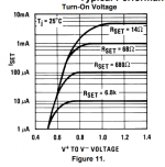

Nice data on the LM334 - thanks for that.
(I don't often use them, for sim reasons - but it is a useful thing for jelly bean purposes; that 100k ish impedance, agrees with my exp; it isn't bad at all for a cheap, settable 2-terminal device - so had to appear on the list)
(I don't often use them, for sim reasons - but it is a useful thing for jelly bean purposes; that 100k ish impedance, agrees with my exp; it isn't bad at all for a cheap, settable 2-terminal device - so had to appear on the list)
Thanks!
Your analysis seems reasonable to me. I'm embarrassed that the measurement method wasn't obvious to me. 🙁
Your analysis seems reasonable to me. I'm embarrassed that the measurement method wasn't obvious to me. 🙁
Found an old thread about a 5.5mA current source, here is a link . I think you could slide the knee to the left (lower voltage) by using a JFET with a smaller |Vpinchoff| such as the J106 or J107 (obsolete), or the MMBFJ109 or MMBFJ110 (current production).


The current mirror / "1V reference" tracks and cancels the temperature dependence of Vbe.are we not basically passing the buck to the current mirror? Or to ask the question differently, how is this better than using an elaborate CCS to bias a ~1V reference, which in turn biases a PNP?
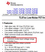
Another way to skin the cat is to use a temperature independent reference and an opamp whose common mode input range includes the top rail, like the super low cost TL072 PJFET opamp, or the super high cost LT1637 "Over The Top" opamp. This also increases the output impedance thanks to enormous amounts of negative feedback.
You start with a bandgap stabilized, zero tempco voltage referenced to the top rail, which is noise reduced by R4-BFC. The opamp + NFB loop ensure that this is exactly the voltage impressed across Rsense. Voila Iout = V/R = constant / constant = constant. Resistors R1 and R2 allow you to use an opamp whose output voltage range does not include the top rail, giving you more flexibility when deciding which opamp to select. Or make R2 a zener if you prefer.
Notice that if you set R2 >= 4*R1 , you can use a much higher bandwidth, decompensated opamp like the LF357. Then you can joyously experiment with sub-50pF capacitors across resistors, to optimize the behavior at 1 megahertz.
_
Attachments
Found an old thread about a 5.5mA current source, here is a link .
I would have never found that thread, thanks! I have a few kinds of JFETs, but none of those; I'll check them out. They do work great in a cascode.
The op amp circuit certainly is over the top. I like it, I wouldn't expect zero tempco to add much value to a regulator, and I'm a bit weary of running an op amp with the inputs and outputs so close to the + rail, but perhaps some strategic level shifting could help. I'll need to study the circuit some more; thanks for sharing.
Thanks!
Your analysis seems reasonable to me. I'm embarrassed that the measurement method wasn't obvious to me. 🙁
You shouldn't be. 🙂 I like to think that learning is what these forums are all about.
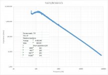
I've attached a few more curves, with the shunt capacitance calculated at a few different points of the curve, to make up for noisy data. The nominal impedance is calculated by averaging 70-140Hz, barring a few exceptions that showed a more "inductive" behavior. Negative shunt capacitance shows up from time to time, and suggests the CCS is inductive / ringing, that the data is noisy, or that the nominal LF impedance is underestimated.
Attachments
-
 MPSA42.jpg83.2 KB · Views: 94
 -
 MPSA18.jpg76.4 KB · Views: 84
 -
 MJE15034G.jpg86.9 KB · Views: 75
 -
 MJE340.jpg84.2 KB · Views: 93
 -
 MJE200.jpg82.6 KB · Views: 84
 -
 KSC3503.jpg83.7 KB · Views: 91
 -
 KSC1845.jpg79.9 KB · Views: 90
 -
 BD139.jpg81.5 KB · Views: 90
 -
 BC550.jpg73.7 KB · Views: 85
 -
 BC337.jpg78.5 KB · Views: 79
 -
 2SC6144SG.jpg79.2 KB · Views: 88
 -
 2SC2240.jpg79.6 KB · Views: 101
 -
 2N2222.jpg77 KB · Views: 86
When I think good current sources, I think of Hans(*):
http://www.designinganalogchips.com/
http://www.designinganalogchips.com/_count/designinganalogchips.pdf
Chapters 3 and 5.
Yes, it is aimed at chip design where you can pick arbitrary areas and ratios, but you can probably see-through to discrete schemes.
(*)Actually Widlar, but Hans is more accessible.
You are talking about the Erdi current source on p.81 and yes it is implementable with discretes, as long as you get a very tight match among the four NPNs named Q5, Q4A, Q4B, and Q4C.
The op amp circuit certainly is over the top. I like it, I wouldn't expect zero tempco to add much value to a regulator, and I'm a bit weary of running an op amp with the inputs and outputs so close to the + rail, but perhaps some strategic level shifting could help.
Don't be frightened. The TL072 is designed and characterized and every unit is tested, with the input common mode voltage at the top supply rail. And the LT1637 is part of a family of chips named Over The Top, because it works correctly with its inputs several volts ABOVE the top supply rail. Check its datasheet, the schematic is wild. Here's more info on the '072
_
Attachments

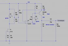
Well, you convinced me. I built a variation of the circuit (attached) on a breadboard.Don't be frightened.
In lieu of the LM4041, I used a green LED and ran a divider off of it. The LED's forward voltage was somewhat sensitive to current as the supply voltage varied, so I replaced R3 with a simple JFET CCS. I didn't have any TL071s on hand, so the unused channel is left floating.
I replaced R2 with another green LED with a ~1.8V forward voltage. R1 is set to 2k.
The low frequency performance is great, likely better than measured as the signal across the sense R is masked by noise, but the high frequency response is a fair bit worse than the BC550 singleton. I know the theory suggests performance should be significantly better, any subtleties I may be missing here? Maybe the TL072 just running out of gain?
Edit: Increasing Vce doesn't seem to change much at all, nor does replacing the led between the op amp output and BJT base with a 6.8V zener...
Attachments
Last edited:
I suggest you discover why the computed value named "shunt capacitance" jumped by more than 100X between the two circuits which both include the same BC560 device.
And since you've got the schematic in LTSPICE already, see whether LTSPICE predicts the same -20dB/decade fall of impedance, and where the rolloff begins ... 150 Hz?
Me personally, when batteries are not involved, I prefer to "run em hot". So I'd drop R6 to 750R myself.
And since you've got the schematic in LTSPICE already, see whether LTSPICE predicts the same -20dB/decade fall of impedance, and where the rolloff begins ... 150 Hz?
Me personally, when batteries are not involved, I prefer to "run em hot". So I'd drop R6 to 750R myself.
You have probably included the opamp in the setup, meaning its PSRR comes into play.
Anyway, here is another idea: it uses 3 transistors, has a poor initial accuracy and a moderately poor temperature stability, but it has a good output impedance and operates down to 0.3~0.4V dropout


This is the temperature stability:

It shows a strong negative tempco, but that's the sim: I suspect that in reality, the Hfe dependence and Vbe will largely compensate one another.
It could be tuned by splitting R3 and connecting R1 to the tap. By varying the tap ratio, the tempco could be ~cancelled.
R4 cancels the dynamic resistance of Q3; it can be omitted if the auxiliary supply is stable; in fact Q3 could be replaced by two Si diodes in this case
Anyway, here is another idea: it uses 3 transistors, has a poor initial accuracy and a moderately poor temperature stability, but it has a good output impedance and operates down to 0.3~0.4V dropout
This is the temperature stability:
It shows a strong negative tempco, but that's the sim: I suspect that in reality, the Hfe dependence and Vbe will largely compensate one another.
It could be tuned by splitting R3 and connecting R1 to the tap. By varying the tap ratio, the tempco could be ~cancelled.
R4 cancels the dynamic resistance of Q3; it can be omitted if the auxiliary supply is stable; in fact Q3 could be replaced by two Si diodes in this case
Attachments
As I suspected, the BC557 model is aberrant: it shows an inverse dependency of beta with temperature, which ruin the compensation.
This is more like it:

This is more like it:
- Home
- Amplifiers
- Solid State
- Building a low-dropout 5mA CCS