ah,sorry it wasnt. The amp was sharing the channel with the jq6500 soundboard. I’ll try to isolate it with a separate supply channel as in your drawing.thnxs, thats the way it was wired in the video and pictures.
That won't be easy with a filterless class-D amplifier. The output signal is a square wave of a few hundred kilohertz of which the duty cycle is modulated.Once I’ll have everything hooked I’m thinking of using the oscilloscope to compare the input and output signal of the pam8403 hopefully somewhere this week.

Interesting, I had no idea 😀. Learning step by step. I appreciate your suggestions and remarks, helps a lot 🙂!That won't be easy with a filterless class-D amplifier. The output signal is a square wave of a few hundred kilohertz of which the duty cycle is modulated.
So while I'm working on figuring out whats going wrong with the PAM8403 I meanwhile continued on soldering the circuit instead of using the alligator clips. That's when I added a 3.5mm switch socket so it's becomes possible to bypass the internal amp and speaker and connect it to an external amp and speakers system.
Now there is some unexpected and strange behaviour going on. When there's nothing plugged into the switch socket, the system functions as supposed (there is some noise however coming from the two mic's channels (not sure if its a groundloop or something else) but its acceptable for now, also it's not consistent, sometimes its louder, and sometimes almost unnoticeable).
The weird things happen when I plug an external amp and speaker (in this case a jbl go2) which should bypass the internal amp and speaker. The external amp+speaker is putting out sound, however there is still some sound coming from the internal amp+speaker. I would say its about 95:5% ratio. The other (to me) very weird behaviour is that in this situation the MIC's are not working anymore. The music from the phone, and the sounds from the soundboard are functioning, but the MIC's aren't. As soon as I pull out the jack from the switch socket the mic's work again.
Now I thought, maybe it had something to do with the wiring of the XLR outs. I disconnected pin 1(ground) and 3 because i thought maybe there could be a signal on pin 3 that was messing up the ground. But disconnecting it didn't make an improvement.
 I checked all the wiring to make sure everything is as I thought it should be. The attached image shows the circuit as I made it. I'm lost on whats going wrong here...
(PS. So maybe you notice I changed the mic-preamp with a different model(k2572), it has stereo output of which I am using R for MIC 1 and L for mic 2, it works pretty decent (on the JBLgo2 when the switch socket it not in the circuit), sometimes there's a bit of noise (not sure if its a groundloop or something else), sometimes there's no noise at all.)
Now there is some unexpected and strange behaviour going on. When there's nothing plugged into the switch socket, the system functions as supposed (there is some noise however coming from the two mic's channels (not sure if its a groundloop or something else) but its acceptable for now, also it's not consistent, sometimes its louder, and sometimes almost unnoticeable).
The weird things happen when I plug an external amp and speaker (in this case a jbl go2) which should bypass the internal amp and speaker. The external amp+speaker is putting out sound, however there is still some sound coming from the internal amp+speaker. I would say its about 95:5% ratio. The other (to me) very weird behaviour is that in this situation the MIC's are not working anymore. The music from the phone, and the sounds from the soundboard are functioning, but the MIC's aren't. As soon as I pull out the jack from the switch socket the mic's work again.
Now I thought, maybe it had something to do with the wiring of the XLR outs. I disconnected pin 1(ground) and 3 because i thought maybe there could be a signal on pin 3 that was messing up the ground. But disconnecting it didn't make an improvement.
(PS. So maybe you notice I changed the mic-preamp with a different model(k2572), it has stereo output of which I am using R for MIC 1 and L for mic 2, it works pretty decent (on the JBLgo2 when the switch socket it not in the circuit), sometimes there's a bit of noise (not sure if its a groundloop or something else), sometimes there's no noise at all.)
If the PAM8403 and loudspeaker produce only treble, it could be capacitive crosstalk somewhere. No idea why the microphones stop working.
OK, I think i found out why the mic stoped working. I've wired as in the picture below.

Something is going wrong in the switch socket. When nothing is plugged. pin 3-4 and 2-5 are connected. When something is plugged, the pins should disconnect. When I measure continuity with the multimeter beep, this is what I can verify. However, when I measure resistance between 3-4 there seems to be a connection. resistance between 2-5 when plugged is 0 ohm as expected. Since the mic signals are mono and only travel through the red wire, the mic stop working.
In this situation the music and sound effects from channels 2 and 3 from the mixer still work since they are stereo signals. Even though the signal through the red wire is blocked the signal is still travelling through the yellow wires.
I guess. I'll have to order a new switch socket, and hopefully this solves the problem.
Yes 🙂, after a few days of debugging I made some progress. The Switch Jack was wired incorrectly. 3 - 4 had to be swapped. Also I split the two mic signals (mono, R only) at the mixer and feed it in the L channel, now when I plug the jack switch the mic signal is fed into both speakers.
Also, the PAM8403 magically stopped clipping after I switched the alligator clips with soldered wires. It's certainly not hifi but sounding OK for the purpose now.
I'm excited I can finally move on to making the enclosure now, however I have a question about the final piece of circuitry I like to add. I want a slideswitch with a led to power the system on and off. Since the current of the rest of the circuit has spikes up to 2A, I was thinking of using a MOSFET for switching the high current circuit.
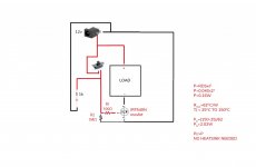
I found a IRF540N MOSFET in my stock. After researching a bit I came up with the following circuit. Since its my first use of such a circuit I would appreciate a lot if someone could check if I haven't done anything incorrectly.
Also, the PAM8403 magically stopped clipping after I switched the alligator clips with soldered wires. It's certainly not hifi but sounding OK for the purpose now.
I'm excited I can finally move on to making the enclosure now, however I have a question about the final piece of circuitry I like to add. I want a slideswitch with a led to power the system on and off. Since the current of the rest of the circuit has spikes up to 2A, I was thinking of using a MOSFET for switching the high current circuit.
I found a IRF540N MOSFET in my stock. After researching a bit I came up with the following circuit. Since its my first use of such a circuit I would appreciate a lot if someone could check if I haven't done anything incorrectly.
Attachments
Great!
I don't see why you need the MOSFET, as there are enough switches that can handle 12 V, 2 A DC. If you do use it, try to figure out what happens when the battery is almost empty. When VGS approaches the threshold voltage, the on resistance increases a lot and the power dissipation might become higher than with a full battery. How much current does the circuitry still draw at voltages that make the on resistance increase to a few tenths of an ohm rather than a few hunderdths?
I don't see why you need the MOSFET, as there are enough switches that can handle 12 V, 2 A DC. If you do use it, try to figure out what happens when the battery is almost empty. When VGS approaches the threshold voltage, the on resistance increases a lot and the power dissipation might become higher than with a full battery. How much current does the circuitry still draw at voltages that make the on resistance increase to a few tenths of an ohm rather than a few hunderdths?
I wanted to avoid shipping costs for a single slide switch (i have low amp rating slide switches in stock, but not a higher amp rating). But from your comment I understand its better to avoid the MOSFET circuit and use a higher amp slide switch?
Now let me try to learn from the second part of your reply (its all new to me so maybe I'm making some silly mistakes). Do you mean that when the resistance of the gate becomes high due too low battery voltage, the heat dissipation might become a lot more than my calculation from when the battery is providing 12v, and that this might burn out the MOSFET?
"How much current does the circuitry still draw at voltages that make the on resistance increase to a few tenths of an ohm rather than a few hunderdths?"
What would be a good number for calculating? Say the battery drains to 10.5V and the resistance of the gate becomes 0.5ohm? -> it would draw a current of 21A and a power of 220W. But I think the gate resistance is not that low at 10.5V....
If I take the gate treshold voltage of 2 volts, and assume the resistance then becomes 0.5 ohms -> it would draw 4A and 8W
In that case the heat dissipation would become problematic, but would the battery really go that low? Isn't it dead way above that value?
Again, sorry if I'm missing the fundamentals and talking nonsense...
I don't think you quite understood me.
According to an oversimplified quadratic model, the on resistance of a MOSFET is inversely proportional to VGS - Vth. The reality is much more complicated, but I think we can use this model as a rough and somewhat conservative estimate.
The Vth of your MOSFET can be anything between 2 V and 4 V according to its datasheet (at room temperature anyway, it gets larger at low and smaller at high temperatures). In your circuit, the battery voltage determines VGS.
Imagine you have a MOSFET with 4 V threshold voltage and a nearly empty battery that only supplies 4.3 V. The VGS - Vth is then one twentieth of the VGS - Vth at which the on resistance is specified, so the on resistance could be twenty times higher than what you calculated on: 0.8 ohm rather than 0.04 ohm.
If your karaoke set still draws 2 A at 4.3 V - 2 A*0.8 ohm = 2.7 V, then your MOSFET will have 20 times more self-heating than you counted on. If the karaoke set has an undervoltage lock-out and draws only a few milliamps at 4.3 V, then there is no issue. By the way, switched-mode power supplies often draw more current at low input voltages than at higher voltages, until they go into undervoltage lock-out.
All in all, I think you have to measure what happens with the karaoke set supply current when you go from 12 V to 0 V.
Thanks for the explanation! I'll check the current when I go from 12 to 0V and see if there's an undervoltage lock-out circuit. I think such an undervoltage lock-out circuit might be useful anyhow to switch off the LED when the voltage becomes too low for the rest of the circuit to operate.
With a previous project I had the situation where the LED was still shining, while the battery voltage was too low for the PCB's to work. But because the LED was still on people thought the device was broken instead of replacing the batteries.
With a previous project I had the situation where the LED was still shining, while the battery voltage was too low for the PCB's to work. But because the LED was still on people thought the device was broken instead of replacing the batteries.
Ah I guess a simple fix would be a zener diode in series with the led 😅. Offcourse it doesnt protect the batteries but thats something else.Thanks for the explanation! I'll check the current when I go from 12 to 0V and see if there's an undervoltage lock-out circuit. I think such an undervoltage lock-out circuit might be useful anyhow to switch off the LED when the voltage becomes too low for the rest of the circuit to operate.
With a previous project I had the situation where the LED was still shining, while the battery voltage was too low for the PCB's to work. But because the LED was still on people thought the device was broken instead of replacing the batteries.
- Home
- General Interest
- Everything Else
- Building a karaoke set; Condenser mic with preamp not loud enough