10 years ago....long time!Just noticed, we joined just a month apart.
My power switch is made of metal and is mounted in the acrylic front panel so is not earthed. Do you think I need to connect it to the enclosure?
Very interesting design and construction, bravo!
Is it possible to have a different memory of signal dB between inputs?
I think, it will be interesting for various sources testing.
For example, input1 to be connecting to a dac1 with -30dB and the input2 to be connecting to another dac2 with -25dB.
Is it possible to have a different memory of signal dB between inputs?
I think, it will be interesting for various sources testing.
For example, input1 to be connecting to a dac1 with -30dB and the input2 to be connecting to another dac2 with -25dB.
Thanks!Looks very good!
I don't want this feature but yes it would be very easy to add this in software.Very interesting design and construction, bravo!
Is it possible to have a different memory of signal dB between inputs?
I think, it will be interesting for various sources testing.
For example, input1 to be connecting to a dac1 with -30dB and the input2 to be connecting to another dac2 with -25dB.
This looks very good, nice work! 😀
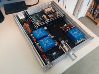
Did your MODU chassis have a pre-cut IEC inlet? Mine has and it's actually really annoying as it doesn't line up with where my PCB mount inlet sits in the chassis, I'd rather have had the option to just cut that myself. Maybe yours did too and you have just enlarged it?
I'll be interested to hear if the aluminium dividers help your noise issue much. Quite often it is a ground issue instead of radiated noise but you now have 3 PSU modules so should have plenty of scope for proper grounding.
Thanks. Nope, mine was blank and I cut it myself.This looks very good, nice work! 😀
Did your MODU chassis have a pre-cut IEC inlet?
I had long wires everywhere too so hopefully shortening, twisting and simplifying the wiring will help too. We'll see. Should be done in a couple days 🙂I'll be interested to hear if the aluminium dividers help your noise issue much. Quite often it is a ground issue instead of radiated noise but you now have 3 PSU modules so should have plenty of scope for proper grounding.
CS3318 modular preamplifier
Interesting preamp project, I have been working on a similar modular multichannel preamp project based on the CS3318 chip. More info:
PreAmplifier v2.0
Perhaps we can share some of our experience.
Interesting preamp project, I have been working on a similar modular multichannel preamp project based on the CS3318 chip. More info:
PreAmplifier v2.0
Perhaps we can share some of our experience.
Interesting preamp project, I have been working on a similar modular multichannel preamp project based on the CS3318 chip. More info:
PreAmplifier v2.0
Perhaps we can share some of our experience.
Great project! Has many similarities with mine. I see you also have an annoying 50hz spike 😉
The 50Hz spike is not so bad at all, the magnitude is really low and completely unhearable with headphones, so no practical problem. I assume part of it comes from a ground loop in the measurement setup and the additional contribution in the CS3318 volume control board is really low.Great project! Has many similarities with mine. I see you also have an annoying 50hz spike 😉
I completely agree. It still annoys me though! I also measured a completely passive preamp and also a single pot and it's there too so perhaps unavoidable when taking measurements with an E-MU device.The 50Hz spike is not so bad at all, the magnitude is really low and completely unhearable with headphones, so no practical problem. I assume part of it comes from a ground loop in the measurement setup and the additional contribution in the CS3318 volume control board is really low.
On your page you state "Signal detection to allow automatic switch off after 15 minutes without signal" as a feature. How did you implement this? Could you draw a schematic of this part?
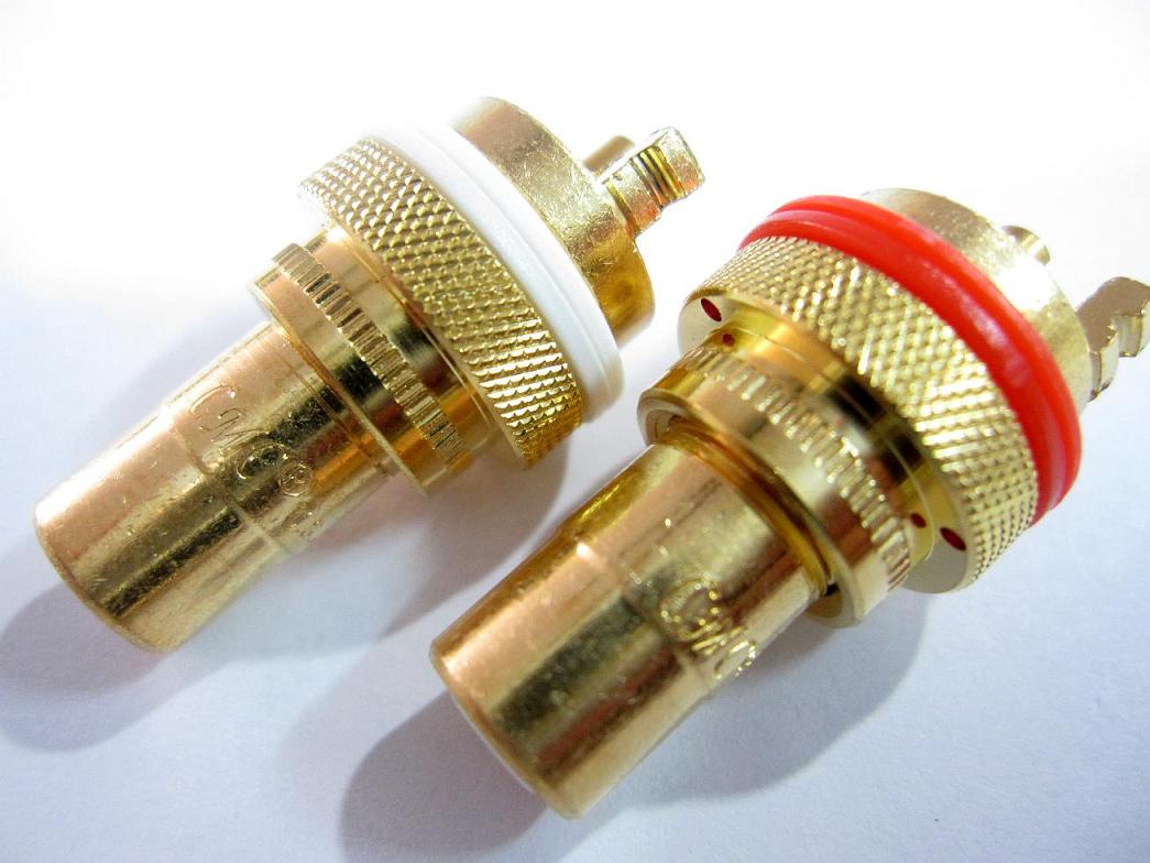
My new problem is that I can't solder cable onto the ground part of these connectors:

Even with my 70W Hakko soldering iron I can't get enough heat into the connector to get the solder to stick properly as the connector is such a large solid piece of metal 🙁
Any body else had this problem?
Even with my 70W Hakko soldering iron I can't get enough heat into the connector to get the solder to stick properly as the connector is such a large solid piece of metal 🙁
Any body else had this problem?
I have the same rca plugs and I don't recall having soldering problems with them although I have a 30 watt soldering iron.
Try with a different solder paste or scratch the surface of the metal a little bit, it should be easier after that.
Try with a different solder paste or scratch the surface of the metal a little bit, it should be easier after that.
My new problem is that I can't solder cable onto the ground part of these connectors:
Even with my 70W Hakko soldering iron I can't get enough heat into the connector to get the solder to stick properly as the connector is such a large solid piece of metal 🙁
Any body else had this problem?
Definitely had the sane problem. I've used a small gas torch to heat the connector up. In my case it was a speaker connector.
Just be a bit gentle with it, it's really hot, about 1400 degr C or so. Just heat it up from a small distance so the tin will melt, not burn ;-)
I'm sure you're aware of that..
I've tried to include a photo, not sure if it works though.
Attachments
Maybe the way the temperature control works on my Hakko iron? It's not on constantly, it just turns on/off repeatedly to maintain a constant temperature. I tried for hours to get it to work and even put the iron on its maximum temperature but no luck.I have the same rca plugs and I don't recall having soldering problems with them although I have a 30 watt soldering iron.
Thanks for the suggestion! A gas torch sounds like it would work but I just bought a cheap 100W iron from eBay for £10. Will try again when it arrives.Definitely had the sane problem. I've used a small gas torch to heat the connector up. In my case it was a speaker connector.
- Home
- Source & Line
- Analog Line Level
- Building a complete Preamp with an Arduino, remote, volume and input control

