lol me too also i ran it by my dad he doesn't want 15's i guess he just wants to use the dual 10's because that's what is there and its less work. So the crossover design is at 4 ohm load? Very kewl then I can get the most out of the amp.The thing I don't like about the peavey woofer is that it's a peavey woofer 🙂
Hello Nines,
You really should stop worrying about "getting the most" of the amp at a 4 Ohm load. Yes the design I am offering happens to be roughly a "4 ohm" speaker, but this is not crucially important at all. The difference between the 100W rating at 8Ohm and 150W rating at 4 Ohm is a difference is listening level that you would barely be able to distinguish on speakers with equal efficiency. (it's like, ~1-2dB difference). In this case, that doesn't even matter because you are going to have an Xmax limitation of about 70WPC at low frequency anyways. To be honest, even that doesn't really matter at this point. This system is going to be capable of 110dB+ without a problem. That's LOUD! (like rock concert loud).
You're going to need to pull that front baffle off and build a cab into it for the mid-range driver, I suggest a minimum 0.5ft^3 for that driver, but the more the better, stuff it with insulation or polyfill or something like that. If you can build it in such a way that the dimensions are somewhat far from a "cube" shape that would be best (try not to have any internal dimensions that are equal). Also, if you could somehow make the rear of the chamber at an angle offset to the front baffle that would be even better. While you have the front baffle off to do this, installing some braces and a thin layer of dampening material on all the inside walls would be a good idea (if that doesn't already exist).
yea I'm not that conserned about wattage anymore I was just saying it's nice. The mid enclosure is going to be 0.5ft^3 sealed right? We don't have a table saw with angle type blades so idk how we would make an angle and if it's sealed I doubt it matters that much. You said earlier that we might be able to use a different sensitivity mid and that it wasn't that important after all? If that is possible a closed back mid would be better so we don't have to build a box for it. I believe the boxes do have poly fill in them already.Hello Nines,
You really should stop worrying about "getting the most" of the amp at a 4 Ohm load. Yes the design I am offering happens to be roughly a "4 ohm" speaker, but this is not crucially important at all. The difference between the 100W rating at 8Ohm and 150W rating at 4 Ohm is a difference is listening level that you would barely be able to distinguish on speakers with equal efficiency. (it's like, ~1-2dB difference). In this case, that doesn't even matter because you are going to have an Xmax limitation of about 70WPC at low frequency anyways. To be honest, even that doesn't really matter at this point. This system is going to be capable of 110dB+ without a problem. That's LOUD! (like rock concert loud).
You're going to need to pull that front baffle off and build a cab into it for the mid-range driver, I suggest a minimum 0.5ft^3 for that driver, but the more the better, stuff it with insulation or polyfill or something like that. If you can build it in such a way that the dimensions are somewhat far from a "cube" shape that would be best (try not to have any internal dimensions that are equal). Also, if you could somehow make the rear of the chamber at an angle offset to the front baffle that would be even better. While you have the front baffle off to do this, installing some braces and a thin layer of dampening material on all the inside walls would be a good idea (if that doesn't already exist).
They have a slot on the bottom for a slot port but it's sealed off atm, we were planning on opening it up and making them ported again I'm just not sure what to tune the port too. The slots are 13.75" W x 3.75" H so what should we tune the boxes too?
I'm not sure we can fit a .5ft^3 enclosure for the mid if we make it out of mdf it's gotta be like 10"W x 7"H x 20"D that is going to take up a lot of room inside the boxes and is really deep. I also don't think we can stack them because the baffle isn't tall enough to get a 6.5" mid and a tweeter on top plus have the woofers where they are.
My dad is ready to order everything tho he wanted to do it tonight but idk if that mid is going to work.
Based on looking at the picture you posted, there appears to be ~12" of space above those woofers, is there not?. You can and should mount the tweeter down partially in-between the woofers, which should reduce the amount of space needed above the top rim of the woofers on the baffle to about 8-9". See the "doodle" in post #164, would that not work? The tweeter is about 4" diameter at the face plate. Mid range is ~6.5" rim to rim. You should mount everything pretty close together if possible.
As far as the box goes internally. You have 8ft^3 of space to work with, there is nothing wrong with sacrificing some of it for the mid-range driver. Even 1-2ft^3 of loss is not going to be a problem at all. If doing an angle cut is not practical don't worry about it. It's just "ideal" to have have the internal shape of a box such that there are as few parallel walls and as many different wall sizes/shapes as possible so as not to cause any pronounced resonances. An old rule of thumb is to shoot for box shape such that the dimensions are in the ratio 0.6 : 1 : 1.6. It doesn't have to be exactly that, just something in the ballpark is a nice plan, and having it such that no wall is an even multiple of another wall is also something to shoot for. most of this box shape stuff is sort of nit picky finer detail stuff that serious builders are going to try to pay attention to. You can emplement as much or as little of it as you can or want to.
A lower efficiency mid is an option, A sealed back mid is an option, but I don't think the results would be better in either case. I think it's worth trying to utilize that dayton mid-range.
Eric
We might be able to fit the 6.5 on top and tweeter in middle but the problem is the sides of the enclosure for the mid behind it have to be way more than 6.5" to get a .5ft^3 box. Heck at 10" wide by 7" the box for the mid has to be 20" long that is really long.Based on looking at the picture you posted, there appears to be ~12" of space above those woofers, is there not?. You can and should mount the tweeter down partially in-between the woofers, which should reduce the amount of space needed above the top rim of the woofers on the baffle to about 8-9". See the "doodle" in post #164, would that not work? The tweeter is about 4" diameter at the face plate. Mid range is ~6.5" rim to rim. You should mount everything pretty close together if possible.
As far as the box goes internally. You have 8ft^3 of space to work with, there is nothing wrong with sacrificing some of it for the mid-range driver. Even 1-2ft^3 of loss is not going to be a problem at all. If doing an angle cut is not practical don't worry about it. It's just "ideal" to have have the internal shape of a box such that there are as few parallel walls and as many different wall sizes/shapes as possible so as not to cause any pronounced resonances. An old rule of thumb is to shoot for box shape such that the dimensions are in the ratio 0.6 : 1 : 1.6. It doesn't have to be exactly that, just something in the ballpark is a nice plan, and having it such that no wall is an even multiple of another wall is also something to shoot for. most of this box shape stuff is sort of nit picky finer detail stuff that serious builders are going to try to pay attention to. You can emplement as much or as little of it as you can or want to.
A lower efficiency mid is an option, A sealed back mid is an option, but I don't think the results would be better in either case. I think it's worth trying to utilize that dayton mid-range.
Eric

How about making the box ~10-11" tall (8.5-9.5" internal dimension w/3/4" wood) (go right to the top baffle so you don't have to use wood there), ~8" wide (~6.5" internal), and the internal depth of the box (~20", or 18.5" internal), (again, using the rear baffle to finish it off). That way you only need 3 pieces of wood per box. A pair of ~10" x18.5" and a single ~6.5" x 18.5"
That gives a healthy ~0.6ft^3 to work in for the mid-range while the box only looses ~1ft^3. You would mount both the tweeter and woofer in that box section.
As far as your port goes. Would it not be simpler to use the full baffle width for a slot port so you only need a single piece of wood to "make" the port?
If practical, a single 22.5" x 15" piece of MDF installed at the bottom of the box to form a slot port should work fine and keep things fairly simple. The position of the baffle that forms the port can vary anywhere such that the port is as little as ~0.5" "tall" up to ~2" "tall" depending on how you want your tuning. 0.5" would technically be ~16hz, which would provide a nice smooth rolloff (f3 40hz and f10 20hz) and would actually yield a timing performance on par with a sealed enclosure through most of the listening range whilst giving a few dB advantage in the very bottom end compared to sealed. Bumping that up to 2" moves the tuning point to ~30hz, resulting in a bit of a bass boost "hump" so to speak centered around 50hz, (f3 ~30hz, f10 ~22hz).
Technically speaking, anywhere in that range, and even a sealed box, would probably sound reasonable. I think I would suggest making it 2" for starters and you can always slide pieces into the slot to change the tuning to see what you like better.
Eric
The baffle is not the whole front of the box we had to change the holes so we cut a piece of mdf and from the woofers up behind the original baffle. I could use the entire top half of the replacement baffle width and height I didn't think about putting the tweeter inside it also. The back is not glued on so we can take the back off. But the front isn't an entire front piece just the tan part you see the rest is the original box. We were going to unblock the port hole and then just make a 4 sided slot to go behind it since there's a slot in the original baffle. I'll see how the box is put together more when we get everything ready.How about making the box ~10-11" tall (8.5-9.5" internal dimension w/3/4" wood) (go right to the top baffle so you don't have to use wood there), ~8" wide (~6.5" internal), and the internal depth of the box (~20", or 18.5" internal), (again, using the rear baffle to finish it off). That way you only need 3 pieces of wood per box. A pair of ~10" x18.5" and a single ~6.5" x 18.5"
That gives a healthy ~0.6ft^3 to work in for the mid-range while the box only looses ~1ft^3. You would mount both the tweeter and woofer in that box section.
As far as your port goes. Would it not be simpler to use the full baffle width for a slot port so you only need a single piece of wood to "make" the port?
If practical, a single 22.5" x 15" piece of MDF installed at the bottom of the box to form a slot port should work fine and keep things fairly simple. The position of the baffle that forms the port can vary anywhere such that the port is as little as ~0.5" "tall" up to ~2" "tall" depending on how you want your tuning. 0.5" would technically be ~16hz, which would provide a nice smooth rolloff (f3 40hz and f10 20hz) and would actually yield a timing performance on par with a sealed enclosure through most of the listening range whilst giving a few dB advantage in the very bottom end compared to sealed. Bumping that up to 2" moves the tuning point to ~30hz, resulting in a bit of a bass boost "hump" so to speak centered around 50hz, (f3 ~30hz, f10 ~22hz).
Technically speaking, anywhere in that range, and even a sealed box, would probably sound reasonable. I think I would suggest making it 2" for starters and you can always slide pieces into the slot to change the tuning to see what you like better.
Eric
I could make the midrange box the full width 19.5" x 11" then it only has to be 8" deep and that's .6ft^ft.
So I want to tune the main box in the same frequency range as a sub woofer then? We tuned my dads sub to around 23hz.
Last edited:
if you make the slot port the width of the baffle, then 1.25" tall is ~23hz tuning.
If you use the existing 3.75 x 13.75" slot, then i would suggest installing the pieces to form the port such that the resulting inside port dimentions are 12.25 x 2.25" with a total port length of ~16". That would be ~23hz.
If you use the existing 3.75 x 13.75" slot, then i would suggest installing the pieces to form the port such that the resulting inside port dimentions are 12.25 x 2.25" with a total port length of ~16". That would be ~23hz.
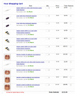
I'll figure it out ok I have the drivers and all the crossover parts you had in your image for a total of $367.44 just waiting to hear we are sure on the crossover heh.if you make the slot port the width of the baffle, then 1.25" tall is ~23hz tuning.
If you use the existing 3.75 x 13.75" slot, then i would suggest installing the pieces to form the port such that the resulting inside port dimentions are 12.25 x 2.25" with a total port length of ~16". That would be ~23hz.
and you've got the components from the second itteration not the first?
$367? hmmmm... lots of shipping cost?
by my math the drivers and the x-over should be under $300 before shipping.
cart should have the stuff from below in it. It would be good for you to look over the network and confirm that I got it all matched up right in the cart.
As far as being "sure." Nope, never going to say it 🙂 Wish someone else would be kind enough to come along and check/critique the x-over.
Attachments
Last edited:
and you've got the components from the second itteration not the first?
$367? hmmmm... lots of shipping cost?
by my math the drivers and the x-over should be under $300 before shipping.
cart should have the stuff from below in it. It would be good for you to look over the network and confirm that I got it all matched up right in the cart.
As far as being "sure." Nope, never going to say it 🙂 Wish someone else would be kind enough to come along and check/critique the x-over.


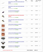
Stupid me... didn't calculate for [4] of the woofers in the price 🙂
Is the price going to work for yall or would you like to scrap it and try for cheaper?
Is the price going to work for yall or would you like to scrap it and try for cheaper?
Well he knew we needed 4 woofers 2 mids and 2 tweeter so he knew id be around $300 idk how we could get it any cheaper?Stupid me... didn't calculate for [4] of the woofers in the price 🙂
Is the price going to work for yall or would you like to scrap it and try for cheaper?
we could try for a lower order x-over all around, use a few "tricks" to get more slope out of the x-overs without as many high cost components, or even take what is there and reduce the cost [some] by switching out everything for electrolytic caps. I think higher end caps on the load carrying side for the high frequency sections are probably worth it though. It's really the inductors that are hard on the budged.
Yea the caps are not going to change the price that much id rather go with good components so they sound nice and wont need replacing. We gotta order a 25ft rca patch cable and some y adapters for his preamp to sub right now hes using high inputs and it sounds horrible lol.we could try for a lower order x-over all around, use a few "tricks" to get more slope out of the x-overs without as many high cost components, or even take what is there and reduce the cost [some] by switching out everything for electrolytic caps. I think higher end caps on the load carrying side for the high frequency sections are probably worth it though. It's really the inductors that are hard on the budged.
Wait a min I only see 2x 25uf caps in the 2nd xover diagram. Yeah I'm looking at the diagram with ur list next to it and I don't see half the components you have in the list.
Last edited:
You have to build 2 x-overs. one per speaker. so everything in the diagram doubles.
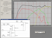
..... I just tried tinkering with some shallower slopes and see lots of problems. I'm going to tinker a bit more but so far I don't like the results.
..... I just tried tinkering with some shallower slopes and see lots of problems. I'm going to tinker a bit more but so far I don't like the results.
lol duh stupid me it's late hehe.You have to build 2 x-overs. one per speaker. so everything in the diagram doubles.
..... I just tried tinkering with some shallower slopes and see lots of problems. I'm going to tinker a bit more but so far I don't like the results.
The following saves some money, but there are numerous things I don't care for about it but heck, it would work.
Attachments
Last edited:
What don't you like about it?The following saves some money, but there are numerous things I don't care for about it but heck, it would work.
The focal is a factory buyout, if for some reason you get a defect and need to do an exchange and they run out of them in the mean time then you would have an x-over designed for drivers that might be hard to source.
In your box I assume you will have ~10-12" of spacing between the centers of the 10" woofers, also with the mid-range positioning I suggested, there will probably be similar spacing to the center of the mid-range. With that spacing, frequencies below ~1100 hz will tend to emanate from these drivers as if it were a single point source. At frequencies above this point, frequencies will eminate more as if they are from 2 separate point sources (and 3 separate point sources where the mids and woofers are kind of "sharing" the load), which causes lobing issues and can "muddy" up what many refer to as "imaging.". With the shallower X-over, there is still a fair amount of content from the large drivers present at only ~10dB down from reference in the 1-6K range. I'm not sure if that's enough attenuation to keep the system operating enough like a single point source to image well.
Tweeter and mid-range both have less protection from low frequency.
The distance from the mid-range to the 10" drivers in the baffle positions I suggested may be less than ideal considering the large overlap. however, alternatives would not likely be an overall improvement.
The originally proposed build with the 12dB and 18dB slopes would probably image radically better than this less expensive build with the shallow slopes.
Eric
- Status
- Not open for further replies.
- Home
- Loudspeakers
- Multi-Way
- Building 3-way speakers