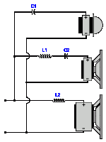
There's a mistake in there that I'd better point out. However, I am sure it is just a slip of the keyboard!My shopping list is:
Pair of Inductors 0.2mH
Pair of Inductors 1.2mH
Pair of Caps 2.2uF
Pair of Caps 22uF
Tweeter use 2.2uF
Midrange use 1.2mH followed by the 22uF Cap.
Woofer use 1.2mH Inductor.
It should read: 'Midrange use 0.2mH followed by 22uF Cap.'
You could attach the components to a section of plywood or softwood using plastic ties (drill holes through the wood to accept the ties).Is a circuit board recommended or should I knock one up out of wood or other material?
Then you can simply solder the necessary connecting wires directly to the components.
P.S. Space the two inductors apart on opposite sides of your board to reduce the interaction of their magnetic fields.
It would be even better if you were to mount the larger coil flat (horizontal) on the board and the smaller one vertical.
It would be even better if you were to mount the larger coil flat (horizontal) on the board and the smaller one vertical.
Thanks Galu.
Will follow your recommendations, particularly the Inductor positions.
The Inductor value was definitely a typo (cut & paste), but will use the correct values when I execute the makeover.
Just sorting out my requirements to recap a pair of B&W MD110's which have old electrolytic parts.
Then I'll get an order going.
Thanks again
Cliff
I have been using polypropylene motor run capacitors in my crossovers with good results. They are a lot cheaper and worth looking at.
Given the low frequency limitations of the midrange, which is really just a big tweeter, we should probably play safe by using a 10uF capacitor instead of the 22uF capacitor.Then I'll get an order going.
I hope it's not too late to add a couple of 10uF bipolar electrolytics to your order.
Last edited:
Not too late.
Great pick up.
Does that raise the frequency step before the midrange tweeter takes over?
What frequency?
Should we alter the inductor values as well to line up?
thanks
Cliff
Great pick up.
Does that raise the frequency step before the midrange tweeter takes over?
What frequency?
Should we alter the inductor values as well to line up?
thanks
Cliff
Last edited:
I want to raise the frequency at which the mid takes over, as it's really just a big tweeter and not a fully purposed midrange driver.
Since you haven't made your order yet, I'll change the component values to suit 2,500Hz and 6,000Hz crossover points. Remember that first order crossovers have shallow slopes so allow a degree of overlap between the drivers.
C1 = 3.3uF; C2 = 8uF; L1 = 0.2mH; L2 = 0.5mH
I stress that this is very much an ad hoc crossover arrangement! Should it prove to be unsatisfactory, you can revert to the original crossover arrangement, but with the advantage of now having different capacitor values to experiment with. 😎
Attachments
Hi Galu.
Just to let you know the Sansui recap project is still on the cards along with a B&W project.
I've had to prioritize for the moment.
cheers
Cliff
Just to let you know the Sansui recap project is still on the cards along with a B&W project.
I've had to prioritize for the moment.
cheers
Cliff
Hi Cliff!
It's good to hear from you. I've been looking out for your return and hoping that all was well with you.
Hopefully, it won't be long before we can continue our crazy crossover capers!
It's good to hear from you. I've been looking out for your return and hoping that all was well with you.
Hopefully, it won't be long before we can continue our crazy crossover capers!
I want to raise the frequency at which the mid takes over, as it's really just a big tweeter and not a fully purposed midrange driver.
Since you haven't made your order yet, I'll change the component values to suit 2,500Hz and 6,000Hz crossover points. Remember that first order crossovers have shallow slopes so allow a degree of overlap between the drivers.
C1 = 3.3uF; C2 = 8uF; L1 = 0.2mH; L2 = 0.5mH
I stress that this is very much an ad hoc crossover arrangement! Should it prove to be unsatisfactory, you can revert to the original crossover arrangement, but with the advantage of now having different capacitor values to experiment with. 😎
Hi Galu.
Sorry to be a nuisance.
Just getting my shopping list together.
A post or 2 before your last the values were altered from 22uF to 10uF, but then the final instruction refers to an 8uF cap.
Did we drop the 10uF?
thanks.
Cliff
Buy the above values.I'll change the component values to suit 2,500Hz and 6,000Hz crossover points.
C1 = 3.3uF; C2 = 8uF; L1 = 0.2mH; L2 = 0.5mH
C1 = 3.3uF; C2 = 8uF; L1 = 0.2mH; L2 = 0.5mH
Buy the above values.
I have 2 x 2.2uF & 2 x 1.0uF
In parallel this totals 3.2uF
Will that be acceptable?
Or will it affect the result sonically?
Perfectly acceptable!
Provided you stay within plus or minus 10% of the component values, there will be no audible effect when using such a simple crossover.
Provided you stay within plus or minus 10% of the component values, there will be no audible effect when using such a simple crossover.
For crossover points inductor values would be L1 = 0.2mH; L2 = 0.5mH.
Hi Galu.
I've held off so far on purchasing the parts because, I needed to assess my cap & parts needs for 3 other sets of speakers, and I was only able to recently harvest some air core inductors from written off Amp.
My meter may not be up to measuring Inductors.
It thinks they are resistors and returns an average value of 0.26 Ω
Is that insufficient in assessing these Inductors?
thanks Cliff 🙂
Last edited:
You got these inductors from an amplifier? 😕
These are unlikely to be the same type of inductors as used in loudspeaker crossovers - perhaps you could supply an image?
If your meter correctly recognises known loudspeaker crossover inductors, then the components from the amp may not be what you think they are.
P.S. For this particular renovation, I would purchase inexpensive components such as NP electrolytic capacitors and ferrite cored inductors. These particular speaker drivers will not benefit from expensive crossover components. Besides, we are only experimenting at this stage, so cheap components are the order of the day.
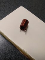
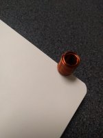
Here are some photos.
These are 17mm high with a 12mm diameter.
I already have the caps.
Poly caps came to aud$40 but already in my possession
Air core 21awg Inductors would be a further aud$19
Leftovers from previous projects.
Is $59 too much to tip into the Silcrons?
Should I keep these caps for quality future projects?
Attachments

Last edited:
The inductance of those inductors is so small that it is not registering on your meter. They are probably in the microhenry (μH) range.
They are therefore not suitable for use as loudspeaker crossover inductors which are in the millihenry (mH) range..
Until we have arrived at a crossover configuration that works satisfactorily with your drivers, you should only use inexpensive components.
Once the final component values are arrived at, you can decide on whether you wish to use better quality components.
I'm regarding this renovation as an opportunity to educate you on how simple crossovers work. Some alteration of component values may be required when you try out the crossover in practice.
Lay your expensive crossover components aside for now.
- Home
- Design & Build
- Construction Tips
- Build time to adjust sound on Sansui Silcron Speakers.