Today, I replaced all heaksinks for the SSLVs with much larger one. Before finding a suitable case for all the components, I have to figure out the best layout. After several trial, finally I come up with this as shown in the picture. I never expected I need such big size case with so many heatsink for a DAC!
Haha, welcome to a club! I used two cases and still could use some more space, 🙂
In my situation two 15 V power supplies - Shunty x 2 took the most room. Great progress. That graphic display looks really cool. Congrats!
Haha, welcome to a club! I used two cases and still could use some more space, 🙂
In my situation two 15 V power supplies - Shunty x 2 took the most room. Great progress. That graphic display looks really cool. Congrats!
Hi AR2
Thanks for your message, I hope I can build something as beautiful as yours😀
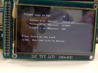
Spent couple of hours and finally have the "SDcardINFO" displays the card info on the GLCD.
I've checked several times to ensure all libraries have been included and the RAW files are in the root directory but still can't display the Bitmap image.
Below are extract from my Arduino code:
#include <Wire.h> // For I2C
#include <EEPROM.h> // We will use the eeprom to store values
#include <UTFT.h>
#include <tinyFAT.h>
#include <UTFT_tinyFAT.h>
#include <avr/pgmspace.h>
#include <Arial_bold_14.h>
.
.
.
.
.
.
myGLCD.InitLCD();
myGLCD.clrScr();
file.initFAT();
myGLCD.setColor(255,255,255);
myGLCD.loadBitmap(0, 48, 400, 144, "SQBX.raw");
delay(4000);
myGLCD.clrScr();
Can anyone spot any error in the above code?
Attachments
Spent couple of hours and finally have the "SDcardINFO" displays the card info on the GLCD.
I've checked several times to ensure all libraries have been included and the RAW files are in the root directory but still can't display the Bitmap image.
Below are extract from my Arduino code:
#include <Wire.h> // For I2C
#include <EEPROM.h> // We will use the eeprom to store values
#include <UTFT.h>
#include <tinyFAT.h>
#include <UTFT_tinyFAT.h>
#include <avr/pgmspace.h>
#include <Arial_bold_14.h>
.
.
.
.
.
.
myGLCD.InitLCD();
myGLCD.clrScr();
file.initFAT();
myGLCD.setColor(255,255,255);
myGLCD.loadBitmap(0, 48, 400, 144, "SQBX.raw");
delay(4000);
myGLCD.clrScr();
Can anyone spot any error in the above code?
Are you using the following, I'm mainly referring to the "tf" after the UTFT
UTFTtf myGLCD(ITDB32WD,38,39,40,41);
The only differnce in mine is the "setColor" see below.
myGLCD.InitLCD();
myGLCD.clrScr();
file.initFAT();
myGLCD.setColor(255,255,255);
myGLCD.loadBitmap(0, 48, 400, 144, "L&T_YRB.RAW");
delay(4000);
myGLCD.clrScr();
Your SD card only appears to be 120 MB maybe that's an issue. I thought the software had been written around 1 & 2 GB cards & maybe 4 GB might work.
Today, I try again to repair the burnt BIII, I replaced the ES9018, checked all Tridents. Put the BIII onto the Legato and power up, NO SOUND🙁
Check all voltage and found the Trident for XO overloaded. Take away the Crystek and voltage resumed to 3.3V. Then try to connect it with Ian's clock board and operate in Sync Mode, but still no "Lock"😕
No Dual Mono BIII at the moment, concentrate to finish the Arduino programme and the connection between WaveIO, OTTO II, Teleporter and FIFO.
I still can't display bitmap on the GLCD. I use the "file.exists" to check if Arduino can detect the file in the SD but was returned a "false"🙁 Does any one know how to use the "findFirstFile" and display the file name?
Below is the code I used to check the file in SD:
Code:
#include <SD.h>
#include <UTFT.h>
#include <tinyFAT.h>
#include <avr/pgmspace.h>
extern uint8_t BigFont[];
extern uint8_t SmallFont[];
// set up variables using the SD utility library functions:
Sd2Card card;
SdVolume volume;
SdFile root;

UTFT myGLCD(ITDB32WD,38,39,40,41);
// change this to match your SD shield or module;
// Arduino Ethernet shield: pin 4
// Adafruit SD shields and modules: pin 10
// Sparkfun SD shield: pin 8
const int chipSelect = 53;

void setup()
{
   myGLCD.InitLCD();
  myGLCD.clrScr();
 // Open serial communications and wait for port to open:
//  Serial.begin(9600);
 //  while (!Serial)
    ; // wait for serial port to connect. Needed for Leonardo only

  myGLCD.setColor(255, 255, 255);
  myGLCD.setFont(SmallFont);

  myGLCD.print("Initializing SD card...",10,10);

 // On the Ethernet Shield, CS is pin 4. It's set as an output by default.
  // Note that even if it's not used as the CS pin, the hardware SS pin
  // (10 on most Arduino boards, 53 on the Mega) must be left as an output
  // or the SD library functions will not work.
  pinMode(53, OUTPUT);     // change this to 53 on a mega

  delay(2000);

  // we'll use the initialization code from the utility libraries
  // since we're just testing if the card is working!
  if (!card.init(SPI_HALF_SPEED, chipSelect)) {
    myGLCD.print("initialization failed. Things to check:",10,30);
    myGLCD.print("* is a card is inserted?",10,50);
    myGLCD.print("* Is your wiring correct?",30,70);
    myGLCD.print("* did you change the chipSelect pin to match your shield or module?",10,90);
    return;
  } else {
   myGLCD.print("Wiring is correct and a card is present.",40,100);
   delay(2000);
  }

  // print the type of card
  myGLCD.print("Card type: ",50,150);
  switch(card.type()) {
    case SD_CARD_TYPE_SD1:
      myGLCD.print("SD1",150,150);
      break;
    case SD_CARD_TYPE_SD2:
      myGLCD.print("SD2",150,150);
      break;
    case SD_CARD_TYPE_SDHC:
      myGLCD.print("SDHC",150,150);
      break;
    default:
      myGLCD.print("Unknown",150,150);
  }
  delay(3000);
  // Now we will try to open the 'volume'/'partition' - it should be FAT16 or FAT32
  if (!volume.init(card)) {
    myGLCD.print("Could not find FAT16/FAT32 partition.Make sure you've formatted the card",10,50);
    return;
  }
delay(3000);
 myGLCD.clrScr();
  // print the type and size of the first FAT-type volume
  uint32_t volumesize;
  myGLCD.print("Volume type is FAT",10,30);
  myGLCD.printNumI(volume.fatType(),220,30);
  myGLCD.print("",220,30);

  volumesize = volume.blocksPerCluster();    // clusters are collections of blocks
  volumesize *= volume.clusterCount();       // we'll have a lot of clusters
  volumesize *= 512;                            // SD card blocks are always 512 bytes
  myGLCD.print("Volume size (bytes): ",40,60);
  myGLCD.printNumI(volumesize,220,60);
  myGLCD.print("Volume size (Kbytes): ",40,80);
  volumesize /= 1024;
  myGLCD.printNumI(volumesize,220,80);
  myGLCD.print("Volume size (Mbytes): ",40,100);
  volumesize /= 1024;
  myGLCD.printNumI(volumesize,220,100);


  myGLCD.print("Files found on the card",00,150);
  myGLCD.print("(name, date and size in bytes): ",00,170);
  root.openRoot(volume);

   file.findFristFile(file.filename);

   if (file.exists("SQBX.RAW")==true)
   {myGLCD.print("file found",10,200);}
  else
   {myGLCD.print("Not found",10,200);}
  // list all files in the card with date and size
  root.ls(LS_R | LS_DATE | LS_SIZE);

}


void loop(void) {

}Finally, I got the "File found" to confirm the Arduino can read file on SD but the "loadBitmap" command doesn't draw the bitmap😕
You don't appear to be using the "tf" UTFTtf myGLCD(ITDB32WD,38,39,40,41);
What size is the SD card?
What size is the SD card?
You don't appear to be using the "tf" UTFTtf myGLCD(ITDB32WD,38,39,40,41);
What size is the SD card?
This is the code that I use to check the SD card content which doesn't require the UTFTtf library.
I use both 128MB and 2GB SD card with the same result🙁
This is the code that I use to check the SD card content which doesn't require the UTFTtf library.
I use both 128MB and 2GB SD card with the same result🙁
I'm out of ideas.
If I send you some code that works with mine then you may be able to track down the problem.
I'm out of ideas.
If I send you some code that works with mine then you may be able to track down the problem.
That's a great suggestion and thanks for your offer🙂
I have sent the code & the raw files good luck
Thanks DQ828, I received the files and tested, but no success. 🙁
I think the problem is related to the file structure in the SD. Thanks a lot for your help and effort.
Hi bigpandahk. I've been following your progress (along with DQ828 and Corpius). I have a dual mono BIII with 4 input S/PDIF board and Sidecar mostly complete (want to add USB input). I was designing a case when I saw the Arduino with LCD displays and had to have one...hopefully...lol
Hi bigpandahk. I've been following your progress (along with DQ828 and Corpius). I have a dual mono BIII with 4 input S/PDIF board and Sidecar mostly complete (want to add USB input). I was designing a case when I saw the Arduino with LCD displays and had to have one...hopefully...lol
Hi SCompRacer
I am also following your BIII project and your connection to the DVD player is great. I will use OTTO 2 and teleporter to connect a DSD sourse and is searching a suitable DVD player.🙂
I have sent the code & the raw files good luck
Hi DQ828
Finally, I manage to display the Bitmap files. The problem is the SD card must not be a MicroSD with adaptor. I hardly find an old SD card and have your bitmaps displayed on the GLCD.
Thanks again for your help and efforts.
This project is far complicate than expected. Just find the best way to connect all the modules is not easy. Thanks for Ian's I2S backdoor which make my life much easier.
I still can't figure out how to switch between PCM and DSD signal since BIII requires different jumpers. According to TPA, SideCar should be designed for this purpose but after checking the details, it can only switching between 4xSPDIF and I2S.
The TTL input of Ian's SPDIF also can't work with the USB WaveIO. Since I don't have another SPDIF source and can't identify which part causes the problem.
Ian's FIFO can't read DSD stream, therefore DSD will go direct to BIII (if I can sort out the jumper problem) and switched by either SideCar or OTTO 2.
BIII + Legato will be powered by SSLV, FIFO + SPDIF + Clock will be powered by 2 x LiPO. I am still thinking how to power the WaveIO by LiPO since it need to drop 1.4V. May be use two diodes!
All you need to do, is place jumpers for DSD - and you can send both PCM and DSD to the pins with no worries. I've done something similar (eXD board, DSD pins to Otto, I2S pins to FIFO to Otto, Otto to Buffalo III with DSD jumpers set.
Works like a champ!
Works like a champ!
Just got the reply from Russ on jumper setting:
Stereo DSD and Stereo PCM?
There is no need to switch anything. 🙂
Even without sidecar You just need to:
connect D1 to D5
then D2 to D4 and D6
then D3, D7 and D8 to GND.
Now nice thing... the Sidecar module does this for you when PCM/DSD input is selected.
Stereo DSD and Stereo PCM?
There is no need to switch anything. 🙂
Even without sidecar You just need to:
connect D1 to D5
then D2 to D4 and D6
then D3, D7 and D8 to GND.
Now nice thing... the Sidecar module does this for you when PCM/DSD input is selected.
connect the SideCar to BIII and check the pin connection. It is different from what Russ mentioned. Only find the following connections are done by SideCar:
D1 to D5 (DSD1)
D2 to D6 (DSD2)
D7 and D8 to GND.
D3 and D4 are not connected to anything by SideCar.
D1 to D5 (DSD1)
D2 to D6 (DSD2)
D7 and D8 to GND.
D3 and D4 are not connected to anything by SideCar.
- Status
- Not open for further replies.
- Home
- Source & Line
- Digital Line Level
- Build Thread for TPA BIII + Ian Async I2S FIFO + OPC NTD1 + Salas SSLV