What I do is listen to a tube amp connected to the MK2 Transformer Interface in 1+1s and it sounds very good.
I also own and listen to the Acoustat Direct Drive amps that I run direct into (no transformer interface) the 1+1s and it sounds even better.
But I am not sure it is all just the OTL that makes the different sound since there is different equalization between the two drive methods.
Dave
I also own and listen to the Acoustat Direct Drive amps that I run direct into (no transformer interface) the 1+1s and it sounds even better.
But I am not sure it is all just the OTL that makes the different sound since there is different equalization between the two drive methods.
Dave
I see a serious contribution to this thread in your future🙂What I do is listen to a tube amp connected to the MK2 Transformer Interface in 1+1s and it sounds very good.
I also own and listen to the Acoustat Direct Drive amps that I run direct into (no transformer interface) the 1+1s and it sounds even better.
But I am not sure it is all just the OTL that makes the different sound since there is different equalization between the two drive methods.
Dave
Wow! big boys indeed; no more need to cascade anything, a straight pair and that's it!Or you can Circlo this guy:
http://ixapps.ixys.com/DataSheet/DS100458B(IXTL2N450).pdf
or some of his buddies:
4500 V Power MOSFETs - IXYS | DigiKey
They would be ideally suited to a CircloMOS... Pete, you have your dd amp

Here is a CircloMOS adapted for extreme voltages:
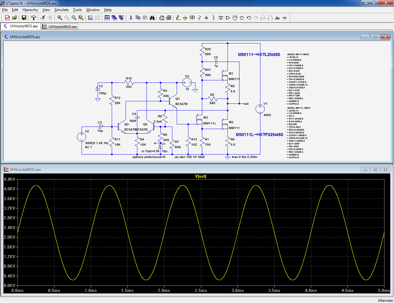
As the complete transistors models look awkward and somewhat incompatible with LTspice, I have used the internal MOS embedded inside the model.
This means no substrate diode, etc, but it gives a rough idea of what to expect.
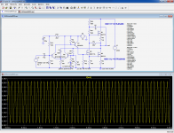
The amplifier is capable of delivering 4kVpp, but only up to 10kHz, because the current necessary to charge and discharge the gates capacitance exceeds the driver's quiescent current beyond that.
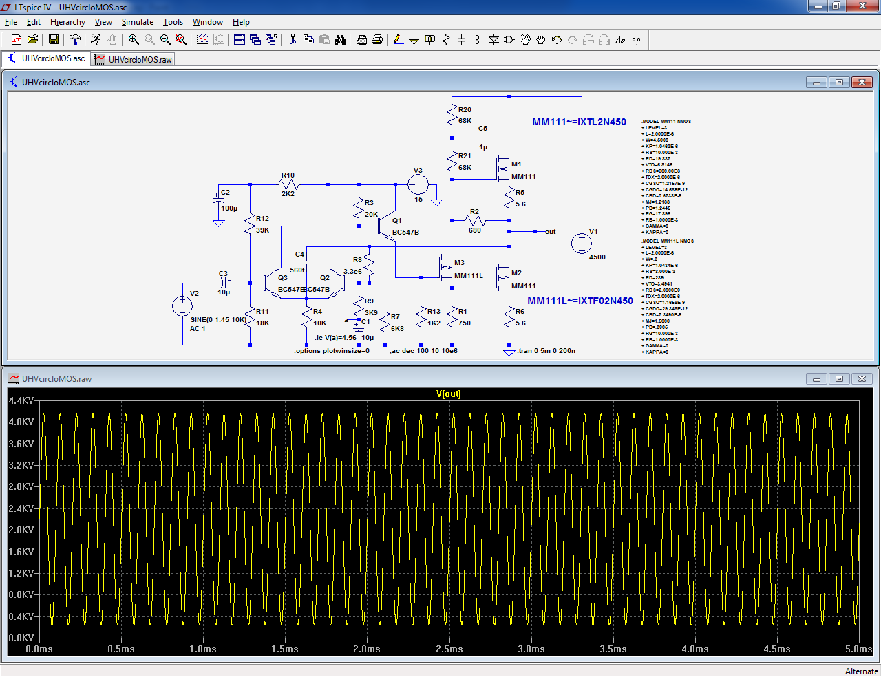
Reaching full power at 20kHz would be possible, but the dissipation in the driver and bias resistors R20 R21 would become really significant.
A workaround would be a floating buffer for M1, but it would require its own, floating supply, which is not simple considering the voltages and frequencies involved.
Anyway, for real musical signals, a full power bandwidth of 10kHz is more than sufficient.
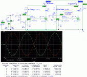
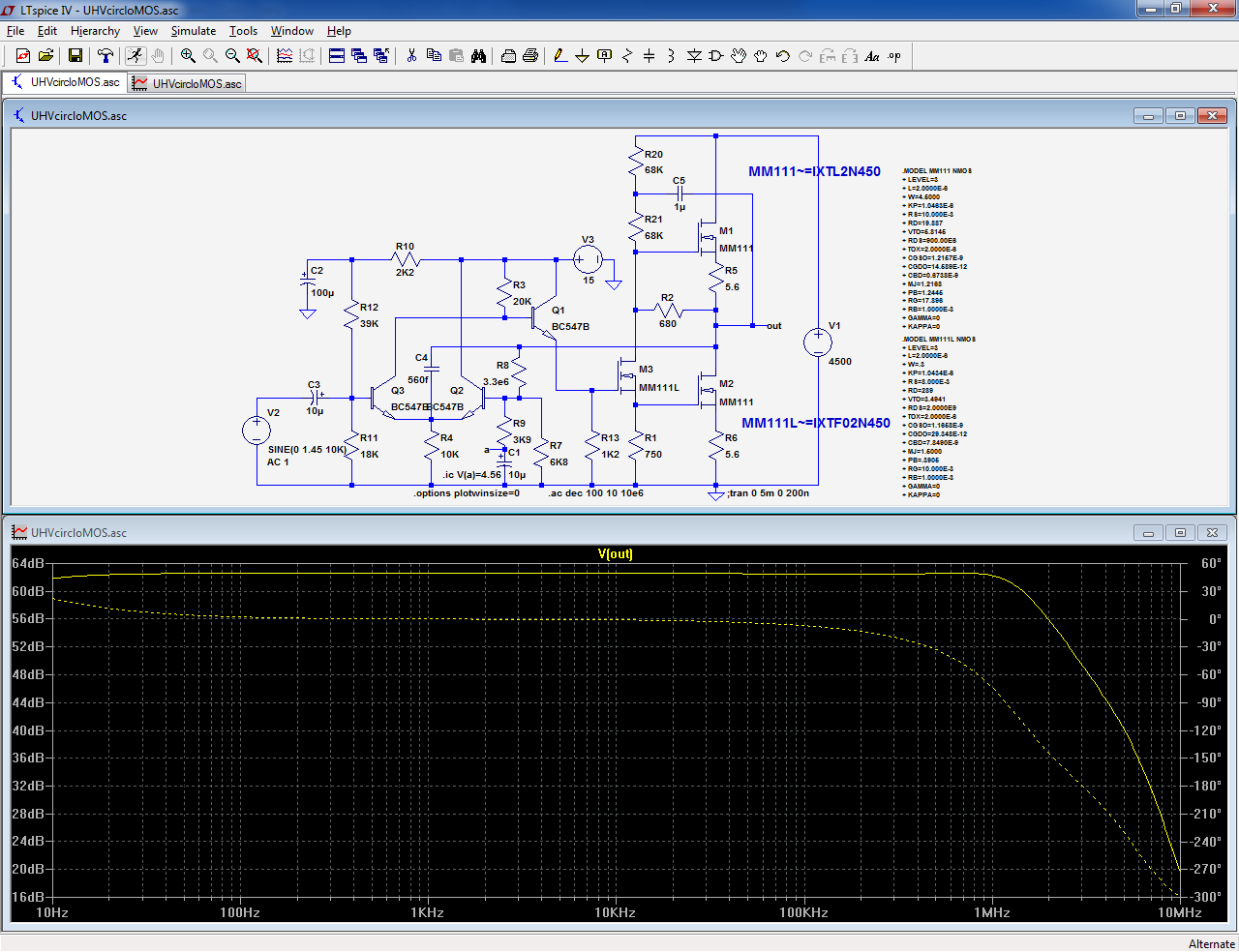
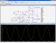
The small signal bandwidth is large enough:
As the complete transistors models look awkward and somewhat incompatible with LTspice, I have used the internal MOS embedded inside the model.
This means no substrate diode, etc, but it gives a rough idea of what to expect.
The amplifier is capable of delivering 4kVpp, but only up to 10kHz, because the current necessary to charge and discharge the gates capacitance exceeds the driver's quiescent current beyond that.
Reaching full power at 20kHz would be possible, but the dissipation in the driver and bias resistors R20 R21 would become really significant.
A workaround would be a floating buffer for M1, but it would require its own, floating supply, which is not simple considering the voltages and frequencies involved.
Anyway, for real musical signals, a full power bandwidth of 10kHz is more than sufficient.
The small signal bandwidth is large enough:
Attachments

Single-ended is an option, of course, but a massive inductor is probably as unattractive as a step-up transformer, and probably even worse since DC bias has to be taken into account. The worst of all worlds...
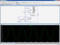
For the sake of simplicity, a semi version can be built, if minimalism needs to dominate over other considerations, like OP current capability, quiescent dissipation, etc:
This circuit looks pretty mundane, yet it includes one or two clever tricks...
Can you spot them?
Attachments
The bottom part is ~ a half-diamond buffer, to isolate the input from the large MOS gate capacitance.
The interesting part is the top one: it is a CCS, but a floating one, because the main device needs to be of the N polarity.
This is achieved thanks to the divider R3 R4. This arrangement cancels the parasitic conductances of the circuit, but here, it goes further: it is overcompensated, meaning it can also compensate for the output resistance of the main MOS, and even for the load: unlike any other drain or plate load, this one actually contributes actively to the output signal, and provides gain and power of its own.
Here, because the load is not resistive but mainly capacitive, going too far in the correction serves no useful purpose, which is why the amount of negative resistance is limited, but it would be possible to use the same mechanism to compensate for a capacitive load, by including a capacitive network across R4.
In fact, this apparently single-ended circuit can work as an implicit push-pull, and it can do so for a variety of load angles, thanks to the weird properties of its drain load: it is an amplifier for which input and output are a single terminal
I'd split R1 and take the output from the midpoint for a 'srpp' derived push-pull Class A
and I think I'd rather split, capacitive bootstrap R2 from M1 source
and I think I'd rather split, capacitive bootstrap R2 from M1 source
I must admit that sensible, proven techniques like SRPP or boostrapping are remarkably effective, but they are not half the fun of more "creative" methods like negative resistance...
Yes, but here the high voltage supply is connected directly to the panels (with long wires across your living room floor) because it is unfeasible to use dc blocking capacitors.I don't think that lethality... Air purifiers, etc. use much higher voltage but are practically never involved in deadly occurences, except when the mains isolation fails.[/URL]
About load, when I built a Sanders-like DD amp, I used a large well-ventilated bank of resistors as the effective loads for the output tubes. The panels were just a slight capacitative load in parallel. Not elegant or efficient, but worked for decades.
B.
Why can't the amps be directly against the panels as with the DD OTLs?Yes, but here the high voltage supply is connected directly to the panels (with long wires across your living room floor) because it is unfeasible to use dc blocking capacitors.
About load, when I built a Sanders-like DD amp, I used a large well-ventilated bank of resistors as the effective loads for the output tubes. The panels were just a slight capacitative load in parallel. Not elegant or efficient, but worked for decades.
B.
Juma, post 5, laid out the liability issues for a person to make a black-box for you that could kill you, your dog, or your kids*, whether or not there are cables across your living room floor and/or whether or not they did it turn-key as a single integrated package with the speakers and/or you signed something that provided the false illusion of a legal release.Why can't the amps be directly against the panels as with the DD OTLs?
B.
*I assume you would turn the amp off once it killed your dog or kids and so no need to say "dogs and/or kids...."** Likewise, I assume your estate would likewise protect your dog after your death.
** I am further assuming your kids are not holding your dog at the time of their joint electrocution nor that the dog was holding your kids; please correct me of those are gratuitous assumptions.
Last edited:
How much current do these types of amplifiers need to produce? Everyone keeps cautioning about the voltage but is the current there to make it lethal?
- Status
- Not open for further replies.
- Home
- Amplifiers
- Solid State
- Build me a ss direct drive ESL amp, please