Search for a good and proven schematic of a single GU50 SE.
Then, modify the single tube GU50 SE circuit this way:
1. Use an SE output transformer that is rated for 2X Watts, 2X current, and 1/2 primary impedance of the single GU50 SE output transformer.
2. Use a power transformer that can deliver 2X current for B+ and filaments.
Pay attention to the rectifier tube and or the rectifier diodes if they can take 2X the current. Also, use 2X the capacitance to get the same ripple voltage. Again, check that the rectifier tubes or diodes can work with 2X the capacitance.
For a power transformer, if this was a stereo amp, you might consider building 2
Mono-Block amplifiers, using 2 of the original power transformer models, one for each mono-block.
3. Use Individual (separate) bias for each GU50. Either 2 adjustable fixed bias pots for each channel, or 2 Individual self bias resistors with individual bypass caps for each channel.
4. Use individual grid stopper resistors for each GU50. Whenever you parallel plates, and parallel cathodes (or even have individual bypass caps to ground for each cathode), Then you need to isolate the RF frequencies from grid to grid, and the individual grid stopper resistors take care of that.
If you do not use the individual grid stoppers, you may end up with a modified Buttler Oscillator in stead of an amplifier stage.
5. Make sure the driver tube can drive the 2X capacitance of the parallel GU50 control grids.
Include the miller capacitance. You may need to parallel the driver tube, in oder to drive the 2X capacitance, so you get the same high frequency bandwidth.
If you parallel the driver tube, then follow the rules for # 3 - 4 above for the driver tubes too.
6. Consider the grid capacitance of the parallel driver tubes, including the miller capacitance. For example, if the single driver tube grid requires a 50k volume pot to get high frequency bandwidth, then you will need a 25k volume pot for the parallel driver tube grids in order to get the same high frequency bandwidth.
7. If the amp uses negative feedback, you may have to adjust the gloabel negative feedback network. That depends on the output transformer you use.
If there is a network that is used as a dominant low frequency pole, for example a series RC network to ground from the driver plate, then with paralleled driver tubes change that RC network to 1/2 the resistance, and 2X the capacitance.
That covers all the major issues.
You should get 2 times the power, and the same bandwidth, and the same distortion at 2 times the power (depending on the quality of the output transformer).
Happy Building, and Happy Listening.
Let Us know how it sounds!
Last edited:
Thanks.Can you not use google, there are a view schematics.
I can't find GU50 PSE schematic.
Attachments
Attachments
Attachments
Last edited:
In Post #2, I said: Search for a good and proven schematic of a single GU50 SE. Then I gave steps to make it a Parallel GU50 SE.
In some posts you have been given several Parallel GU50 SE schematics. Nice. However, the important words are: 'Good and Proven' schematic. But . . . Post #7 has 320V to 400V B+, 470 Ohm screen resistor, and both cathodes paralleled to 75 Ohms to ground. And there is no fixed bias either. I believe that with Only 75 Ohms self bias the tubes will cook and self destruct. We need to go back to 'Good and Proven' Schematics, I do not believe the one in post #7 qualifies. I do not really have the time to check out the others that have been posted.
Instead: I hope someone participates in this thread who has built, tested, and listened to one of these schematics, or another schematic that they have built, tested, and listened to.
There are lots of un-proven schematics on the web that have never been successfully built, tested, and listened to.
I want you to be able to build a working and satisfying Parallel GU50 SE amp.
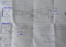
I find two schematics of GU 50In Post #2, I said: Search for a good and proven schematic of a single GU50 SE. <snip>
1. GU 50 SE schematic: You help me modify to PSE.

2. GU 50 PSE already completed. Can I buil follow this?

Thank you.
The GU50 is notoriousfor having arather large spread in characteristics. One tube will run hotter then the other using this schematic. I suggest looking at the biasing, perhaps going for a mix of cathode resistor AND adjustable negative grid voltage
What do you need the extra output power for? A GU50 SE will deliver almost as much power as most 300B SE designs
What do you need the extra output power for? A GU50 SE will deliver almost as much power as most 300B SE designs
I have to take us back to my earlier statement:
"Find a proven and tested circuit".
Now, I add: "and one that has been reliably run for many hours, turned on and off multiple times" . . . Reliability.
On the surface, those look OK. But, very quickly I find some shortcomings in the design of both of those schematics. At least for now, I will not list the errors I found already, because I am sure I can find more errors.
I am working on a commercial amplifier now that someone else modified, and that has no documentation, and has some serious engineering problems. I have had enough of that.
Get back to a fully proven and reliable design.
Come on fellow forum readers, did any of you build, test, and run a GU50 amp for a month of Sundays?
TDHien59,
Have you ever built a tube amp from scratch? I do not mean build a kit.
I mean finding and purchasing the individual correct parts, planning the layout, spacing, and orientation of the parts (like power transformer, choke, and output transformer), drilling the chassis, etc. Then after building the amp and checking the wiring, checking some resistances at critical points. Then powering up the amp, and testing the operational voltages and currents of the amp.
Thanks. I can do it myself, but can't analyze the schematic.TDHien59,
Have you ever built a tube amp from scratch? I do not mean build a kit.
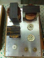
My amp is building, it is monoblock:
Attachments
May be 10W or more. SE is not enough for me unless 845, 211... I have made EL34 SE but the power not suitable for my speaker.The GU50 is notoriousfor having arather large spread in characteristics. One tube will run hotter then the other using this schematic. I suggest looking at the biasing, perhaps going for a mix of cathode resistor AND adjustable negative grid voltage
What do you need the extra output power for? A GU50 SE will deliver almost as much power as most 300B SE designs
TDHien59,
I found a few things I would change about the schematics in your Post #12. There may be some more changes that I missed to make the amp work reliably.
Schematics of Post # 12.
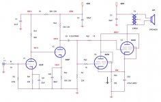
First Schematic:
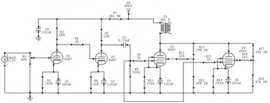
The 6H6pi has 130V on the upper SRPP cathode. But it has to swing 62V more positive to get the GU50 grid to 0V (max power out). That puts the upper cathode at 192V peak. I could not find the spec for the maximum cathode to filament voltage. And the 6H6pi has 5V on the lower cathode. You will have to elevate the filament on the 6H6pi so that both the upper and lower cathode voltages do not exceed the maximum cathode to filament voltage spec for the upper and lower sections of the tube. This is one reason I do not like SRPP circuits. You may have to connect the coupling caps to the upper cathode, because of the input capacitance of 2 triode wired GU50s.
You will need a second coupling cap, and need to duplicate the complete bias circuit (have to have one bias circuit for each GU50). Then you need a second 30 Ohm cathode sense resistor for the other GU50. You need to change the output transformer to 2.125k Ohms (can use 2k). It needs to be 2 times the watts rating, and 2 times the current rating of the original 4.25k transformer. The only direct connections from one GU50 to the other is the plates, and the filaments. You need 83mA more current in the B+ power supply, to power the GU60. And you need more current for the 2nd GU50 filament.
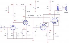
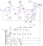
Second Schematic:
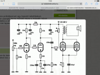
Rk2 8200 Ohm is bypassed by a 10uF 100V cap. But the cathode is at 98.5V. Use a 10uF 200V cap. You may have to elevate the 6H6P filament voltage. I do not know what the cathode to filament max voltage spec is. Each GU50 needs its own grid stopper resistor. Use two 1k resistors. Connect each one right at the GU50 tube socket, then back to the 82k and 0.22uf cap. Each GU50 needs a 2x 857 Ohm resistor = 1714 Ohm cathode resistor Use a separate 1700 Ohm resistor and separate 470uF cap for each cathode (do not connect the cathodes together). This helps the current balance of the two GU50 tubes.
I recommend using two 100 Ohm resistors, one on each screen, the other ends connect to the plate. The GU50 and 6H6P takes some time to warm up. The 480V will be more than that at power-up, and so the 320V B+ may raise to more than 400V. So change the 0.22uF to a 600V rating.
I found a few things I would change about the schematics in your Post #12. There may be some more changes that I missed to make the amp work reliably.
Schematics of Post # 12.
First Schematic:
The 6H6pi has 130V on the upper SRPP cathode. But it has to swing 62V more positive to get the GU50 grid to 0V (max power out). That puts the upper cathode at 192V peak. I could not find the spec for the maximum cathode to filament voltage. And the 6H6pi has 5V on the lower cathode. You will have to elevate the filament on the 6H6pi so that both the upper and lower cathode voltages do not exceed the maximum cathode to filament voltage spec for the upper and lower sections of the tube. This is one reason I do not like SRPP circuits. You may have to connect the coupling caps to the upper cathode, because of the input capacitance of 2 triode wired GU50s.
You will need a second coupling cap, and need to duplicate the complete bias circuit (have to have one bias circuit for each GU50). Then you need a second 30 Ohm cathode sense resistor for the other GU50. You need to change the output transformer to 2.125k Ohms (can use 2k). It needs to be 2 times the watts rating, and 2 times the current rating of the original 4.25k transformer. The only direct connections from one GU50 to the other is the plates, and the filaments. You need 83mA more current in the B+ power supply, to power the GU60. And you need more current for the 2nd GU50 filament.
Second Schematic:
Rk2 8200 Ohm is bypassed by a 10uF 100V cap. But the cathode is at 98.5V. Use a 10uF 200V cap. You may have to elevate the 6H6P filament voltage. I do not know what the cathode to filament max voltage spec is. Each GU50 needs its own grid stopper resistor. Use two 1k resistors. Connect each one right at the GU50 tube socket, then back to the 82k and 0.22uf cap. Each GU50 needs a 2x 857 Ohm resistor = 1714 Ohm cathode resistor Use a separate 1700 Ohm resistor and separate 470uF cap for each cathode (do not connect the cathodes together). This helps the current balance of the two GU50 tubes.
I recommend using two 100 Ohm resistors, one on each screen, the other ends connect to the plate. The GU50 and 6H6P takes some time to warm up. The 480V will be more than that at power-up, and so the 320V B+ may raise to more than 400V. So change the 0.22uF to a 600V rating.
Last edited:
What speakers do you use?
") On polish site a guy bought GU50 based amp and it was total mess inside. He started to rebuild it from scratch. You can check this link and use google or other translator. Audio-Akustyka Auris, wzmacniacz dla odważnych - www.forum-trioda.pl I can ask him if he would share the schematic of his amp. Will let you know if I know something more.
On polish site a guy bought GU50 based amp and it was total mess inside. He started to rebuild it from scratch. You can check this link and use google or other translator. Audio-Akustyka Auris, wzmacniacz dla odważnych - www.forum-trioda.pl I can ask him if he would share the schematic of his amp. Will let you know if I know something more.
Radek
TDHien, what speakers do you have? Sometimes it's better to change speakers than build bigger ampMay be 10W or more. SE is not enough for me unless 845, 211... I have made EL34 SE but the power not suitable for my speaker.
On polish site a guy bought GU50 based amp and it was total mess inside. He started to rebuild it from scratch. You can check this link and use google or other translator. Audio-Akustyka Auris, wzmacniacz dla odważnych - www.forum-trioda.pl I can ask him if he would share the schematic of his amp. Will let you know if I know something more. Radek
I follow your idea to draw the schematic second again:TDHien59,
I found a few things I would change about the schematics in your Post #12. There may be some more changes that I missed to make the amp work reliably. <snip>
Attachments
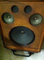
My speaker is no name, no information.TDHien, what speakers do you have? <snip>
Attachments
- Home
- Amplifiers
- Tubes / Valves
- Build GU50 PSE