Hi Kevin,
-Chris
I thought that statement was meant to cover everything. Sorry for the misinterpretation.The PLL he is using to recover the 38kHz subcarrier in theory should take care of all of that. Adjusting the loop bandwidth requires just a simple filter, should be covered.
Yes, agreed. It might be easier to bias a Curl type buffer using N and P channel JFets, gates and sources ties together. Should be very low distortion and automatically track with supply voltage changes.I'd also look at that transistor follower, I'd set the input bias to ~1/2Vcc for best headroom. It may be clipping depending on what VCC actually is.
Yup. That creates the L-R information for the demod. Any pollution here affects both channels.The PLL he is using to recover the 38kHz subcarrier in theory should take care of all of that.
-Chris
IDK, this project looks to be more trouble than it's worth. Growing more complicated than other methods. Some projects don't always work out...
Some people insist on re-inventing the wheel... 😱
Does this valve work the same as a double anode sheet beam tube, like a 7360 or 6JH8? I ask because it's specified for sync separator use, so maybe not a continuous beam reaches the anodes. Just a shot in the dark.
All good fortune,
Chris
All good fortune,
Chris
Hi Chris,
looking at the anode curves, it does appear so as long as you drive the grids properly. Different method, same result would be my guess. I think the grids would have much higher gain (need a lower signal level). So with grid bias, the cathode current is lead between the plates. With deflection plates, it would be a push-pull thing like a scope tube. I have both, I should try and hook them up one of these days. The combined curves of the 6JH8 look a lot more linear, but who knows as the two tubes were not tested the same way.
See: https://frank.pocnet.net/sheets/049/6/6HS8.pdf
and the 6JH8 here: https://frank.pocnet.net/sheets/049/6/6JH8.pdf
Hi wiseoldtech,
-Chris
looking at the anode curves, it does appear so as long as you drive the grids properly. Different method, same result would be my guess. I think the grids would have much higher gain (need a lower signal level). So with grid bias, the cathode current is lead between the plates. With deflection plates, it would be a push-pull thing like a scope tube. I have both, I should try and hook them up one of these days. The combined curves of the 6JH8 look a lot more linear, but who knows as the two tubes were not tested the same way.
See: https://frank.pocnet.net/sheets/049/6/6HS8.pdf
and the 6JH8 here: https://frank.pocnet.net/sheets/049/6/6JH8.pdf
Hi wiseoldtech,
Why not? People like to play and it is a fantastic way to learn. I'll be reinventing the wheel when I design a couple MPX units for upgrading some of my tuners, and to add stereo to a pair of nice tube tuners missing theirs. The levels are way off with the tube tuners. One is a Fisher FM-100 that my dad kicked a coil off off, the other is a Sherwood S-2200 that was ordered as a mono tuner even though an MPX unit was normally fitted (cheap bugger).Some people insist on re-inventing the wheel...
-Chris
I'm not smart enough to parse out how the 6HS8 works from the data sheet. At first blush it doesn't seem very linear, but just as likely I don't understand it. The famous use of the type 7360 was as a double-balanced modulator (like LM1496) in classic HF band coms. Here it had low level signal on G1 and large ("local oscillator") voltage on the deflection plates. The 6JS8 works similarly. I'm just not sure about the 6HS8.
Since these are mathematically multipliers, the process is closely related to sampling, and will have aliases and a requirement for a reconstruction LP filter. Very interesting topic; much thanks to the OP.
All good fortune,
Chris
Since these are mathematically multipliers, the process is closely related to sampling, and will have aliases and a requirement for a reconstruction LP filter. Very interesting topic; much thanks to the OP.
All good fortune,
Chris
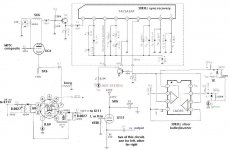
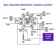
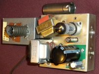
Made a little more progress. Seems I had the cathode of the 6HS8 mis-biased, was 1.9V, looking at the tube datasheet,http://tubes.tubeampdesign.com/sheets/135/6/6HS8.pdf looks like I should have it at 0.7V. An ordinary silicon diode does that. (This chassis had been an electronic volume control
 and I forget to pay it mind) Less distortion, but it's not done yet.
The 67KHz filter messes up separation, so I removed it.
The 6HS8 is driven by a pair of square waves at 38KHz, so the respective plates are either "on" or "off". Very little in between.

The 67KHz filter messes up separation, so I removed it.
The 6HS8 is driven by a pair of square waves at 38KHz, so the respective plates are either "on" or "off". Very little in between.
Attachments
Last edited:


It would be even nicer if you eliminated the PLL. I would use a 19 kHz filter, frequency doubler, all can be done quite simply with tubes.
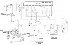
Did more work on it, seems I was getting interference from SCA subcarriers at 67KHz. Sounds like a swishing noise. I reconfigured the 6C4 buffer to give me a lower impedance signal that I then attached a 67KHz trap to. I think it reduced this problem (I have to listen to quiet passages).

67kHz intermod is a problem with the classic switching-type stereo demod. Remember that there are many types of modulation used on the 67kHz sub, mostly FM, but the 67kHz carrier modulating signal could be audio, FSK, really, anything that fits. There were also 92kHz SCAs too, and then digital spread-spectrum schemes that went beyond straight FM and just took up the whole spectrum block between about 58kHz and 98kHz. The point is, that's impossible to trap effectively.
So, take a baseband signal with a block of hash of some kind centered at 67kHz and then take a hard-switching stereo demod producing harmonics in that band, and you have a wonderful intermod soup. Using analog filtering to isolate the two bands becomes a phase mess because for the switching demod to maintain separation through the audio band it has to have excellent phase linearity in the baseband, or some means to phase comp whatever filter is being used. So these are hard problems to solve in the analog world, always were, and exist in the transmitter stereo generators as well.
Analog solutions gravitated towards non-switching matrix decoders, or the utilization of analog multliplier to demod the DSB subchannel. Essentially, you don't hard switch, you accurately demond the L-R then recover L and R in a matrix.
Yes, HD Radio signals elevate the stereo noise floor, but its generally a broad spectrum noise and should not "swish".
The tool you need to sort this out is a low frequency spectrum analyzer (0-100kHz, swept) and a good clean FM alignment generator as a reference. These are very old tools, so hit eBay.
Some more progress! I wanted to reduce the size of the switching square wave as seen on the 6HS8 plates. Kept the diode, and used a combination of a 47K resistor, which in turn feeds a 4.7uF cap and 2.2meg resistor (in parallel) to the B+ the 6HS8 plate resistors connect to. Goal is the shrink the amplitude of the square wave, without impacting the audio signal. The cap creates an average voltage, charged by the diode and 47K resistor. The DC voltage gets created by the resistor divider of the 47K and the 2,2meg resistors. There's still some square wave, but at a much lower amplitude than the one you'd see on the 6HS8 plates. And easier to filter, using the 0.0027uF cap across the 47K resistor. Also acts like a deemphasis filter (the time constant may be off, though).

Using a 'scope, I can see the audio riding on a 38KHz near triangle wave, but one of my goals was to make this wave lower amplitude.
Using a 'scope, I can see the audio riding on a 38KHz near triangle wave, but one of my goals was to make this wave lower amplitude.
Attachments
Last edited:
Theoretically true, but not so much in practice. The combination of a switched-inversion stereo demod and an HD signal is not a good one.Oh, about 15% of FM stations have SCAs.
HD doesn't show up on the FMed carrier, the HD signal is placed some distance from the main FM carrier something like 150KHz above and below.
HD Radio Self-Noise
Don't forget that the FCC now permits HD carriers to be injected at -14dBc, a 6dB increase from what it was originally at -20dBc, if adjacent channel circumstances permit. That doesn't help the analog noise floor at all, in fact it becomes much worse. It does make the average BERT lower in the HD signal, making HD reception much more solid.
Historically, this problem can be mitigated by mixing a bit of 38kHz back in, controlling phase and amplitude, and nulling it at the output at the cost of stability. You can also notch it out of the output too, but that's often harder to do too. Or just don't switch with a square wave. No reason you couldn't do a stepped digital waveform with far lower harmonics than a square wave and still use the 6HS8.One drawback of my scheme is that the resulting left and right channels have this big 38KHz waveform in addition to the audio. I reduced it some by connecting a 470pF cap across the left to right channels (the 38KHz waveforms are inverted compared to each other, but this cap may reduce separation on treble). That made the cathode follower happier, but it's still present. Your audio amp may not like it.
Here is a sound sample of my decoder. Pretty good separation, maybe some distortion, I have 50-50 odds of having the left and right channels correct. 🙂
The encoding into an mp4 seems to have made the sound a bit more "swishy"
The encoding into an mp4 seems to have made the sound a bit more "swishy"
Attachments
Last edited:
I would like to suggest you are far more likely to run into a 57khz subcarrier today than any holdovers at 67 or 92. RDS information carrier on the 57 is in wider use than the traditional subs ever were.
EV3
EV3
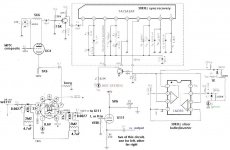
A little more tweaking. Backed off on the input signal level couple dB. Ended up having to make up some gain to drive the chip.
Found a better mp3 to mp4 converter web site MP3 to MP4 online file converter

Some classical music I decoded to stereo off an FM station, sound clip attached.
Sounds pretty good.
Found a better mp3 to mp4 converter web site MP3 to MP4 online file converter
Some classical music I decoded to stereo off an FM station, sound clip attached.
Sounds pretty good.
Attachments
Hi wa2ise,
I really like where you are going with this. My computer doesn't have sound, but your reports are good enough for me.
Yes, signal levels can make a huge difference in performance.
-Chris
I really like where you are going with this. My computer doesn't have sound, but your reports are good enough for me.
Yes, signal levels can make a huge difference in performance.
-Chris
I just realized what the resistor values on the 6C4 are, I'd recommend increasing them to 10 - 12K.
Progress!
Progress!
 And paying more attention, got it right.
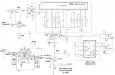
Oh, I figured out how to tell left from right. I compared my left and right outputs to a known set of left and rights from another FM stereo tuner.
...Wanted the "not stereo" indicator to show "stereo" instead. One of those tasks you think you can do in your sleep....
??
Attachments
- Home
- Source & Line
- Analogue Source
- Build a FM stereo decoder using chip and tube