I wanted to post this recent build by Doug De Young (the more productive half of Bug Amps). it's a gorgeous build and an elegant circuit. I can't wait to listen to it.
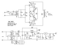
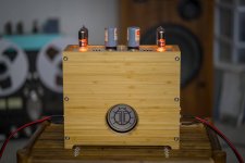
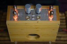
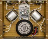
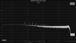
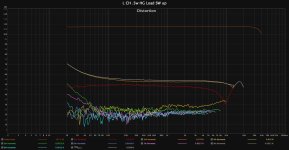
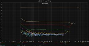
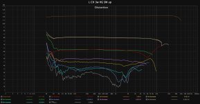
The amp employs a pair of 6E5P in a class A PP design with input transformers. The input txs are vintage JBLs with a number of taps that Doug has used to include switchable gain. For an amp with DC heaters, it's very quiet. The amp has respectable distortion and frequency response:
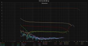
I'm sure Doug will drop in to answer questions.


The amp employs a pair of 6E5P in a class A PP design with input transformers. The input txs are vintage JBLs with a number of taps that Doug has used to include switchable gain. For an amp with DC heaters, it's very quiet. The amp has respectable distortion and frequency response:


I'm sure Doug will drop in to answer questions.
Interesting amplifier. Can you describe teh circuit Doug. Is the 6Э5∏ siuliar to any NA or Euro tubes? What are te specs for the phase split trap?
dave
dave
Last edited:
6Э5П - easy 🙂
It is actually a LTP, But with 2 separate by DC tails for better idle current balance, and cathodes connected by a cap on AC.
Phase is split by 150k grid leak resistors. Specs of JBL transformers are visible on pictures.

It is actually a LTP, But with 2 separate by DC tails for better idle current balance, and cathodes connected by a cap on AC.
Phase is split by 150k grid leak resistors. Specs of JBL transformers are visible on pictures.
Last edited by a moderator:
good for your Doug:
Good to see you here on DIYAudio.
An elegant design for wonderful tube.
I like the presentation package. The bug design is great.
Good to see you here on DIYAudio.
An elegant design for wonderful tube.
I like the presentation package. The bug design is great.
Waveborn has it exactly right, as usual! The 6e5p is a cool little tube because it’s got a fair bit of gain and huge transconductance. Like a 6j43p. That makes it ideal for a small single stage amp like this. Though single stage doesn’t really describe it well as I count the step up input transformer as the first gain stage really.Interesting amplifier. Can you describe teh circuit Doug. Is the 6ℨ5∏ (couldn’t find a cyrillic miroir umaged E) siuliar to any NA or Euro tubes? What are te specs for the phase split trap?
dave
As Waveborn pointed out the CCS on the tail is split in two so that the current balance in the output transformer can be essentially perfect. All AC current flows through the caps between the cathodes. This also cancels distortion and forces class A operation. I matched all the npn BJTs for current gain before I installed them so the single 2.2v regulated supply is a global bias setting for the whole amp. I hope that’s elucidating.
the CCS on the tail is split in two so that the current balance in the output transformer can be essentially perfect
I believe i saw similar in a Nany Huey, and the discussion as to how it works compared to Allen Wright’s common CCS for the output tubes.
I love simple elegant amplifier slike this.
dave
Nice! I saw it at Facebook as well!
What is the load switch meant for?
Why do you have the 50nF cap there? I saw people using big value resistors to "bias" the caps. In some prototypes I used an adjustable one to act as the "harmonizer resistor" used by Western Electric, I will find the relevant thread.
Just yesterday I was going through the film caps catalogue from mouser and saw some nice 100uF/63V caps, for people that do not like electrolytics 🙂
Here is the thread https://www.diyaudio.com/community/...e-for-imd-reduction-work-yes-no-maybe.406808/
What I like most about these little amps is that they are an endless testbed for small changes 🙂 and one doesn't break his back moving it around 🙂
One last question, which OPTs are you using? Are they commercially available?
Congratulations again and many thanks!
I like the design of that amplifier.
Matching of the 51 Ohm emitter resistors assures excellent current balance, as long as the 2N222 are good quality.
The output transformer Loves matched quiescent current.
Those large capacitance caps need a resistor across the little 0.05 uFcap that goes to ground. It does not need to be low resistance (that would disturb the good results that comes from the constant current sinks).
Compare the resitance value you use versus the triode wired pentodes you use.
You need to know the u of the tube when it is triode wired (use the u of g2 to g1).
Each cathode presents an impedance of: 1/Gm Ohms + plate load RL/u Ohms (series total). You want the resistor across the 0.05uF to be much larger than that cathode impedance.
That resistor keeps the bypass caps minus terminals more negative than their positive terminals during all Class A signal levels.
- and + indicates electrolytics, and they need a correct polarity charge across them.
I would not call this a classical LTP stage.
In most LTP stages, the cathodes are DC connected directly together (or at least DC connected together through a metering resistor).
Have Fun Listening!
Last edited:
The 50nf can be found experimentally. Due to unequal capacitance and phase shift in the primary halves of the output transformer the differential action may cause an oscillation at high frequency, typically above the audio band. The cap breaks the differential action at high frequency to prevent this.Nice! I saw it at Facebook as well!
What is the load switch meant for?
Why do you have the 50nF cap there? I saw people using big value resistors to "bias" the caps. In some prototypes I used an adjustable one to act as the "harmonizer resistor" used by Western Electric, I will find the relevant thread.
Just yesterday I was going through the film caps catalogue from mouser and saw some nice 100uF/63V caps, for people that do not like electrolytics 🙂
Here is the thread https://www.diyaudio.com/community/...e-for-imd-reduction-work-yes-no-maybe.406808/
What I like most about these little amps is that they are an endless testbed for small changes 🙂 and one doesn't break his back moving it around 🙂
One last question, which OPTs are you using? Are they commercially available?
Congratulations again and many thanks!
The outputs are a AliExpress find and are amorphous C core. The seller still has them listed.
https://a.aliexpress.com/_mKQ0QFk
The load switch adds a bit of series resistance if the source used is of very low Z. The input transformer is very sensitive to loading.
Thanks for all the answers, all makes sense now! Nice to see the OPTs getting to about -1dB at 30kHz.
I like the design of that amplifier.
Matching of the 51 Ohm emitter resistors assures excellent current balance, as long as the 2N222 are good quality.
The output transformer Loves matched quiescent current.
Those large capacitance caps need a resistor across the little 0.05 uFcap that goes to ground. It does not need to be low resistance (that would disturb the good results that comes from the constant current sinks).
Compare the resitance value you use versus the triode wired pentodes you use.
You need to know the u of the tube when it is triode wired (use the u of g2 to g1).
Each cathode presents an impedance of: 1/Gm Ohms + plate load RL/u Ohms (series total). You want the resistor across the 0.05uF to be much larger than that cathode impedance.
That resistor keeps the bypass caps minus terminals more negative than their positive terminals during all Class A signal levels.
- and + indicates electrolytics, and they need a correct polarity charge across them.
I would not call this a classical LTP stage.
In most LTP stages, the cathodes are DC connected directly together (or at least DC connected together through a metering resistor).
Have Fun Listening!
The npn BJTs and 51R resistors were all matched to achieve the lowest level of core dc.
Thanks for mentioning the missing bias resistance for the electrolytics. I did include it on the pcb and in the actual amp there is a 2m value in the position. I just forgot to place it on the schematic. However it’s not as important as one might think. If one cap is reversed biased the other will be forward biased and so still won’t flow excessively. This is how non polar electrolytes are constructed I believe. Just two polar caps with reverse polarities in series. While testing the circuit in the design phase I couldn’t tell a difference in operation when the biasing resistance was present or not.
I know some people like to adj that value to “fine tune” the amount of differential action and so the amount of 2nd order cancellation but I just used a large value there because I want all the cancellation I can get. I’m not concerned about a push pull stage having a dominant third order component. That just means it’s working properly. That’s just my opinion of course. 😀
Doug De Young,
I believe the issue of not using the proper DC voltage across the electrolytic is two things:
1. Keeping the electrolytic at its specified capacitance (uF).
2. Long lifetime.
As to the 0.05uf capacitor to keep the circuit from oscillating . . .
The 2N2222 transistors bases are connected from DC to RF (all the way beyond the ft cutoff frequency of the transistor).
And, the transistors collectors are connected from Audio to RF (all the way beyond the ft cutoff frequency of the transistor).
The Alpha cutoff frequency of a transistor is 1.2 x the ft cutoff frequency of the transistor.
Oscillators have happened intentionally, and non-intentionally at 1.2 x ft (which is the Alpha cutoff frequency).
Design an amplifier, and get an oscillator. Design an oscillator and get an amplifier.
Oscillations occur, because the circuitry and parasitics around a transistor cause it to work as a common base transistor stage at RF frequencies,
at the same time the transistor is operating as a common emitter stage at DC and audio frequencies.
All circuits are full of parasitic inductance and parasitic capacitance, as well as the capacitance of transistors and tubes, and the inductance of the transistor and vacuum tube leads.
Given that, and depending on the wiring layout, wire lengths and position, you have a dual transistor dual Colpitts oscillator.
Usually, a bead on each base lead, or a 100 Ohm resistor in each base lead will prevent any oscillation.
Just another way to do it, that should not require the 0.05uF cap.
Look under a rug, and you will find dirt.
Look at a circuit, and a [second] circuit is hidden in there . . . an RF circuit
Have fun with these kinds of amplifiers.
I built this amp from Doug's schematic in 2021, it is surprisingly good. I made a video of the build. Mine doesn't look as good as Doug's (but no one's builds look as good as his). I have loaned it out and got nothing but positive reactions. I still use it.

Sounds like you know more about this than I do. Though I’m not sure the BJTs are the source of the oscillation because a previous version of this circuit used a TIP50 and oscillated at the same frequency. Though when I tested with a different transformer the frequency of the oscillation changed. I’ve also used this kind of ccs before with with choke loaded stages and resistance loaded stages without issues.
Your build is amazing!! Your feedback really inspired me to build my own version.I built this amp from Doug's schematic in 2021, it is surprisingly good. I made a video of the build. Mine doesn't look as good as Doug's (but no one's builds look as good as his). I have loaned it out and got nothing but positive reactions. I still use it.
Last edited by a moderator:
Doug De Young,
When I mentioned the ft cutoff and the Alpha cutoff of BJTs, I was misleading.
Those are the practical top frequency limits that can sustain an oscillation.
I would like to know which transformer you changed, that changed the frequency of oscillation.
Input, Or Output?
Think of the transistor and parts, wiring, and the parasitic capacitances and inductances as the frequency determinants of the oscillations (*).
When those frequencies are much lower than the ft cutoffs and Alpha cutoffs, the oscillation frequency will be determined by (*) above;
The same frequency for the 2N2222 and the TIP50.
In my many different jobs and hobby circuits, I have always found BJTs to have much more of a tendency to oscillate, than how often most tube circuits will oscillate.
The input transformer may be part of the reactance, and the output transformer reflecting reactance to the plate + screen (triode wired), from there to g1, and g1 to the tube cathode . . . all can contribute to the reactances that the BJT "sees".
Resistors are great Q killers, and they have nearly flat reactances versus frequency, only parasitic C and parasitic L of lead wires affect that.
One of my circuits used a 12AY7 in parallel, with an IXYS 900V current source. The grids were in parallel, only separated by two 1k grid stoppers, and the cathodes were connected directly to each other, and the plates were connected directly to each other. Wow! that created an oscillator.
The combination of the parallel triodes, and the IXYS CCS reactance was not good. Chicken or Egg (tube or IXYS)? Who cares, istead I attacked it
I fixed it, by connecting two separate 1k resistors, one from each plate to the IXYS CCS plate load.
I had to live and learn.
Oh . . . And I still love that circuit in Post # 1!
Last edited:
The output transformer was changed. The reason being was I designed this at around the same time I designed and built a separate similar amp with 6j43p tubes. I ended up using the output transformer I designed this circuit with in that other amp. So when I wanted to build this circuit I had to redesign it with a different output transformer. That is when I discovered that the oscillation frequency was different with the new output transformer. That was before I decided to change the BJT to a different device. Though none of this makes anything you’ve said incorrect.
Doug De Young,
You are a persistent and creative designer and builder.
One of my observations through my lifetime:
Never believe Marketing . . .
2N2222 ft = 300 MHz
TIP50 ft = 10MHz
Those are Absolutely True And Correct at specified quiescent DC currents and voltages.
But, Marketing likes to use the very best quiescent conditions to make you think their BJT will work in your circuit that operates at X MHz.
To get there, you need the same quiescent conditions, ft is almost always worse at any other quiescent condition.
Coming from a Jaded Marketeer (me - 5 years in Marketing).
And I loved that job. I jumped through hoops to actually help our customers, including giving them the knowledge of what was going on.
Oh, and looking at the pictures in Post # 1, I hope all the readers noticed something that can "Bug" us . . . the drawing of a Bug from a transformer schematic symbol.
Last edited:
- Home
- Amplifiers
- Tubes / Valves
- Bug Amps 3W push-pull 6E5P amp