Just read the thread regarding the Passive preamp by HarryHaller, and got inspired. http://www.diyaudio.com/forums/showthread.php?s=&threadid=2608&highlight=passive+preamp
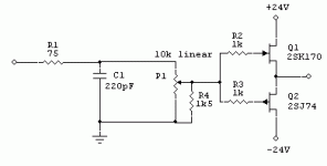
So I quickly drew up this schematic, anything wrong with it? I found a cheap alps 10k motorized pot ($4), so this is going to be real cheap... I think it's worth a try.
What do you think?, suggestions?
/Freddie
So I quickly drew up this schematic, anything wrong with it? I found a cheap alps 10k motorized pot ($4), so this is going to be real cheap... I think it's worth a try.
What do you think?, suggestions?
/Freddie
Attachments
Connect the sources of the fets with a small value trim-pot to adjust for dc offset. The wiper is now your output.
Regards,
Jam
Regards,
Jam
Konnichiwa,
Well, as drawn the worst case input impedance is around 1200 Ohm. I'd rather scale up the Calues by a factor 10 or so, meaning a 15K lawfaking resistor and a 100K Pot.
Sayonara
Freddie said:So I quickly drew up this schematic, anything wrong with it? I found a cheap alps 10k motorized pot ($4), so this is going to be real cheap...
Well, as drawn the worst case input impedance is around 1200 Ohm. I'd rather scale up the Calues by a factor 10 or so, meaning a 15K lawfaking resistor and a 100K Pot.
Sayonara
Member
Joined 2002
Could this schematic be used to drive a gain clone. ? I was thinking about maybe Building one for my small amps that i have completed..?
You'll definitely need some source degeneration; the 50 ohm pot will help, but you'd do better putting a hundred or so ohms in each source lead, then select devices (or, gasp, servo) to minimize output offset.
The input resistor, R4, is much too small. At higher volume control settings, you'll be putting quite a load on the source components. And unless you have TOTAL confidence in the source components, I'd capacitively couple the input. That will make output DC nulling with an integrator easier, too.
The input resistor, R4, is much too small. At higher volume control settings, you'll be putting quite a load on the source components. And unless you have TOTAL confidence in the source components, I'd capacitively couple the input. That will make output DC nulling with an integrator easier, too.
Konnichiwa,
With the selected J-Fets and if they are selected for an Idss that makes sure that the maximum dissipation is not exceeded no further degeneration is neccesary. That is not only my own experiences, but also that of John Curl and Erno Borbely. Adding any more source resistors actually not only increases the output impedance, it also makes (surprisingly) the buffer less linear....
Sayonara
SY said:You'll definitely need some source degeneration; the 50 ohm pot will help, but you'd do better putting a hundred or so ohms in each source lead, then select devices (or, gasp, servo) to minimize output offset.
With the selected J-Fets and if they are selected for an Idss that makes sure that the maximum dissipation is not exceeded no further degeneration is neccesary. That is not only my own experiences, but also that of John Curl and Erno Borbely. Adding any more source resistors actually not only increases the output impedance, it also makes (surprisingly) the buffer less linear....
Sayonara
Well, as drawn the worst case input impedance is around 1200 Ohm. I'd rather scale up the Calues by a factor 10 or so, meaning a 15K lawfaking resistor and a 100K Pot.
Sayonara
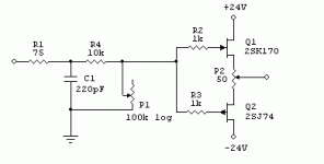
Yes, 1200 ohms is a little low. The only reason why I chose the 10k linear pot, is that I can get a motorized version for $4.. But I will choose a 100k log pot instead in shunt mode.
You'll definitely need some source degeneration; the 50 ohm pot will help, but you'd do better putting a hundred or so ohms in each source lead, then select devices (or, gasp, servo) to minimize output offset.
The input resistor, R4, is much too small. At higher volume control settings, you'll be putting quite a load on the source components. And unless you have TOTAL confidence in the source components, I'd capacitively couple the input. That will make output DC nulling with an integrator easier, too.
Mr. Borbely himself doesn't use any source resistance at all. He said that a DC offset can be as low as 1mv with good matching. But I have included the 50 ohm put anyway. I will try the circuit without extra source degeneration resistors.
My sources have no DC offset and my power amplifier is capacitor coupled, so I will not place a cap at the input.
However thanks for the suggestions🙂
/Freddie
Attachments
Could this schematic be used to drive a gain clone. ? I was thinking about maybe Building one for my small amps that i have completed..?
Yes, it will probably work ok, if you don't need voltage gain.
/Freddie
Re: Motorized log pot
Here in sweden you could look at Farnell,I bought a 50kohm motorized ALPS pot...not cheap(about 400 skr),but I haven´t found a motorized pot anywhere else.....
/Nicke
Freddie said:Anyone know where to get cheap motorized log pots?
/Freddie
Here in sweden you could look at Farnell,I bought a 50kohm motorized ALPS pot...not cheap(about 400 skr),but I haven´t found a motorized pot anywhere else.....
/Nicke
Mr. Borbely himself doesn't use any source resistance at all.
How does he thermally stabilize the offset?
Why not omit the law-faking resistor at all ? Me myself I adjust the listening volume until it is pleasant to my EAR, I don't pay any attention to which direction the loudness knob actually points.
Regards
Charles
BTW:
Some pots have ganging problems at the both ends. I reduce this at the lower and by introducing some small resistors (at the upper end the influence is much smaller). I am not able to reduce the loudness to zero anymore this way, but if I want no sound at all there are other means ........ !
Just put the FETs as close as possible. Maybe you can glue them together, to keep the temperature same.
Sajti
Sajti
I don't know if this guy ships to Sweden, but the price for a motorized audio taper Alps pot is low:
http://www.brigarelectronics.com/
Also, Farnell carries the 50k "blue velvet" motorized pot.
http://international1.farnell.com/S...tml?_DARGS=/common/prodsearchform_inone.jhtml Part #697-930
http://www.brigarelectronics.com/
An externally hosted image should be here but it was not working when we last tested it.
Also, Farnell carries the 50k "blue velvet" motorized pot.
http://international1.farnell.com/S...tml?_DARGS=/common/prodsearchform_inone.jhtml Part #697-930
Konnichiwa,
The usual way I suspect. Take the two Transistors and mechanically combine them. I tend to use them superglued (very little glue) back to back (flat face to flat face)....
Simply select for identical Idss and you can even drop the 50 Ohm pot. Drift is pretty low.
Sayonara
SY said:
How does he thermally stabilize the offset?
The usual way I suspect. Take the two Transistors and mechanically combine them. I tend to use them superglued (very little glue) back to back (flat face to flat face)....
Simply select for identical Idss and you can even drop the 50 Ohm pot. Drift is pretty low.
Sayonara
As long as you keep the load impedance over 5-6kOhms one N-JFET will be sufficient and IMHO better. Complementary pair will drive better heavier loads but these are quite rare.Freddie said:What do you think?, suggestions?
Those gate stoppers resistors will not do much of anything IMHO.
Check this link.JasonL said:Could this schematic be used to drive a gain clone. ? I was thinking about maybe Building one for my small amps that i have completed..?
Pedja
There's also an old plan for a passive buffered preamp you may wish to read:
http://www.stereophile.com/showarchives.cgi?54
http://www.stereophile.com/showarchives.cgi?54
- Status
- Not open for further replies.
- Home
- Amplifiers
- Solid State
- Buffered Passive Preamp