very nice job VladimirK. If you get a moment perhaps you could measure it into 1K, just to see how it performs with a very hard load?
very nice job VladimirK. If you get a moment perhaps you could measure it into 1K, just to see how it performs with a very hard load?
It is no problem, I could report it tomorrow morning. I guess I could measure Rout also. It is expected near 120 Ohms. However, jfets used in this schematics allow even higher idle current and less Rout. I really believe this schematics could drive 600 Ohms Rin of power amp and could be useful in professional audio field.
That's a good idea, to see the Rout and see if it can drive 600 R. (If it can drive 600 R then it might be good for direct drive of many headphones such as the new Beyer T1).
That's a good idea, to see the Rout and see if it can drive 600 R. (If it can drive 600 R then it might be good for direct drive of many headphones such as the new Beyer T1).
I guess, for headphones, universal and excellent schematics would be a similar buffer, but with 2SK60 SIT transistors. Rout will be few ohms, with idle current in the range of 1 ampere. But I realize, that it is more a dream, than reality. 10K volume control will also be needed.
Many thanks for that direction... I will search for information on 2SK60.
I still hope you can measure your circuit tomorrow!
I still hope you can measure your circuit tomorrow!
I have measured output impedance with the input being shorted. Immittance meter was connected to the output socket. This instrument sends to a connected device sine signal at various frequencies, and displays measured impedance module Z and phase angle between voltage and current Fi. For pure capacitive load Fi=-90deg, pure resistive Fi=0, pure inductive Fi=+90deg. I have got the following:
F(kHz) 0,025 1 10 100 200 500 1000
Z(Ohms) 147,2 147 146,8 146,8 146,9 146,8 103,4
Fi(deg) -0,02 -0,07 -0,04 -0,08 -0,14 -0,37 +14
F(kHz) 0,025 1 10 100 200 500 1000
Z(Ohms) 147,2 147 146,8 146,8 146,9 146,8 103,4
Fi(deg) -0,02 -0,07 -0,04 -0,08 -0,14 -0,37 +14
Last edited:
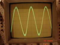
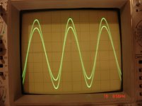
14V peak to peak is about 40mW into 590, so that is a very fine result. Also I like the consistentcy of the output impedance (at normal frequency).
I know that it is not possible to exactly judge distortion from an oscilloscope screen, but as far as we can see it does look very good.
Thank you for posting your results. I am sure many people will like your circuit, and I will build this circuit for myself in the future.
I know that it is not possible to exactly judge distortion from an oscilloscope screen, but as far as we can see it does look very good.
Thank you for posting your results. I am sure many people will like your circuit, and I will build this circuit for myself in the future.
14V peak to peak is about 40mW into 590, so that is a very fine result. Also I like the consistentcy of the output impedance (at normal frequency).
I know that it is not possible to exactly judge distortion from an oscilloscope screen, but as far as we can see it does look very good.
Thank you for posting your results. I am sure many people will like your circuit, and I will build this circuit for myself in the future.
Thank you, I must transfer all gratitudes to Salas, who has attracted attention to the shunty approach, reported also by Borbeley and Waagbo, and to Nelson and John Curl for the buffer solution.
The main things I have learned from this project are that
1) Power Supply solution can be more important than schematics itself
2) use schematics with constant current consumption from main PS, if it is not the case - use current source + shunty || schematics combination.
This approach is not easy to implement, but many of us do not look for easy things in DIY, we look for perfection.
Last edited:
I like the prototype construction look and the scope labeling in Cyrillic. Is it a Russian mil spec scope? That low Rds Teledyne Crystalonics Jfet you used is not common. Must be NOS and metal can? Where you source?
Just 10k load is the lowest hi-fi power amp load you will normally find, 600Ohm could be in some pro gear. Very nice job. Well done. Did you put it to the listen yet?
Just 10k load is the lowest hi-fi power amp load you will normally find, 600Ohm could be in some pro gear. Very nice job. Well done. Did you put it to the listen yet?
I like the prototype construction look and the scope labeling in Cyrillic. Is it a Russian mil spec scope? That low Rds Teledyne Crystalonics Jfet you used is not common. Must be NOS and metal can? Where you source?
Just 10k load is the lowest hi-fi power amp load you will normally find, 600Ohm could be in some pro gear. Very nice job. Well done. Did you put it to the listen yet?
Salas, this project has been inspired in great part by your participation at DIYAUDIO, and I also a supporter of shunt ps approach now. The scope is of ordinary spec, nothing special (50MHz). I use this model because it does not have fans and operates very quiet. Before I used 100MHz scope, that was terribly noisy. Actually, I use russian KP903A parts, that are complete analog to CP650. I indicate CP650 because their datasheet is present in the net. Unfortunately, CP650 are expensive, nearly 17 USD/pc, while KP903A can be sourced in Russia for 2USD/pc.
I continue listening of this new preamp with 50W Zen9 (10K input resistance). This shunty schematics sounds really better than similar buffer preamp with ordinary serial stab. Feeling of real event is better, very natural sound stage and timbre.
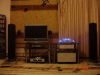
You can see this buffer preamp in my system, together with the 50W Zen9, Shanling CD-T1500 player and PS Audio Power Plant Premier. Significant is that Pass-Style DIY equipment is coming even to most distant places of the world (12 hours difference with California) and pushing out good industrial gear from systems of users.
Attachments
Thanks for the update and the pic. Why the PS Audio? Non frequency stable, and amplitude varying mains? Still a few Greek people live in Tashkent, Uzbekistan till today?
Thanks for the update and the pic. Why the PS Audio? Non frequency stable, and amplitude varying mains? Still a few Greek people live in Tashkent, Uzbekistan till today?
Power Plant Premier got good reviews and was recommended by some friends. However, if somebody would recommend a solution clearly proved to be better than PS Audio, I would be grateful for this. I am almost satisfied with the Premier, except that its fan is slightly audible.
I guess few greek people are still living in Tashkent. A sister of my wife had one of them as a friend (20-15 years ago), even when he already moved to Greece. He came frequently to Tashkent due to some business.
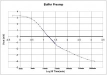
With a capacitorless buffer one is usually concerned with its thermal stability. I did a 24-hours experiment, measured output voltage at one of the channels. As one can see from the enclosed picture, reaching thermal equilibrium is very long process, since the case is heavy and and heat source is weak. But variation of few mV at the output I guess is quite admissible.
Attachments
Happens in DCB1 too +/- 1mV. Takes an hour. People report that it comes across a bit better subjectively too after that time, but its not controlled info. +/- 3-4mV play I think its non issue with your build too. Very nice. Happy listening, and congratulations. Its a very good and very personal control unit made with seldom to us parts in a far away land. Very Sci-Fi. 
After few weeks of listening I am still happy as in the first day. This pre + modified Zen9 reveals the best synergy I ever hoped to achieve. Thank you Salas for encouraging people in using shunt PS. This is not easy, but result is excellent. In order to continue the line of constant current consumption from PS, I plan to make a 50W Return of Zen based on RF-MOSFETs, and to compare with current Zen9. Since both RetOfZen and Zen9 are actually like output stages and need decent drivers, I hope that this pre could solve both tasks.
Did somebody try these buffers? Are there listening reports? It seems that we shall come to John Curl's linear module (double differential) along this line. For me, its more attractive now some 20dB gain powerful preamp, in order to try follower-based power amp.
Last edited:
- Status
- Not open for further replies.
- Home
- Amplifiers
- Pass Labs
- Buffer Preamp with Shunt PS