I plan making this buffer preamp which is supposed to drive 600 ohms input impedance of power amp. Could somebody comment this solution? I hope that the simple shunt-like power supply provides enough supply snubbering and decoupling betwenn the channels.
Attachments
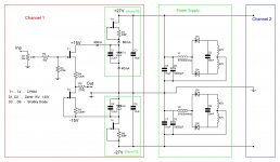
Make C1,C2 big. 1000uF. The Zeners will need noise filtering and they present relatively low impedance.
Make C1,C2 big. 1000uF. The Zeners will need noise filtering and they present relatively low impedance.
Using of good electrolytic at this position is possible, also shunted by good film cap. But do we need shunt PS solution in this case, don't we get the same with plain serial PS? Choice of very good caps seems to repair any active PS drawback.
What you have here is shunt stabilization, not regulation, you got no error loop with gain. It will be silent, but not that stiff. I like your simple solutions, I suggest you breadboard it first and then test a series solution too, and see what you prefer. In my DCB1 the shunt regs boosted it a lot subjectively, had it on series before, same thing for Juma with his BF862 preamp, he upgraded from series to a simple current mirror shunt reg. Good caps don't fix performance in my experience, they just let out better what is already available.
P.S. Also see that your R5 will make the T2 CCS run at about 1/3 its JFET's free IDSS. Good for thermal stability.
P.S. Also see that your R5 will make the T2 CCS run at about 1/3 its JFET's free IDSS. Good for thermal stability.
What you have here is shunt stabilization, not regulation, you got no error loop with gain. It will be silent, but not that stiff. I like your simple solutions, I suggest you breadboard it first and then test a series solution too, and see what you prefer. In my DCB1 the shunt regs boosted it a lot subjectively, had it on series before, same thing for Juma with his BF862 preamp, he upgraded from series to a simple current mirror shunt reg. Good caps don't fix performance in my experience, they just let out better what is already available.
Thanks a lot for the explainations. Just for my better understanding what we are aimed for with shunt regs, I imagine it so that one must measure a slope of the current vs time curve from the moment of step-wise increase in current demand by the the circuit. Any cap has parasitic inductance and resistance, as well as any active device, hence the curve slope is not vertical. But I red somewhere, that Zener is a fastest device in this respect, its reaction period is less than 1ns, while for more complex shunt reg schematics the reaction time will be more than 10ns. Am I wrong?
... P.S. Also see that your R5 will make the T2 CCS run at about 1/3 its JFET's free IDSS. Good for thermal stability.
Thanks. I knew thermal stability criterion for a j-FET as Vgs=Vpinch-off - 0,66V. Usually it is suitable for low Vpo parts. In the present case Vpo close to 5V, and at 5-0,66=4,34V gate bias Id will be too low. Not sure is this thermal stability criterion the same as 1/3 of Idss. I would love if correct is 1/3 Idss. T1 and T2 must be a selected pair and be in close thermal contact. Usually it is enough for keeping output voltage within +- 2mV. Thermal stability point could contradict to other requirements, like idle current needed and power dissipation admittable.
Thanks a lot for the explainations. Just for my better understanding what we are aimed for with shunt regs, I imagine it so that one must measure a slope of the current vs time curve from the moment of step-wise increase in current demand by the the circuit. Any cap has parasitic inductance and resistance, as well as any active device, hence the curve slope is not vertical. But I red somewhere, that Zener is a fastest device in this respect, its reaction period is less than 1ns, while for more complex shunt reg schematics the reaction time will be more than 10ns. Am I wrong?
You are not wrong. Its only it is not a reg this one. Its stable as a Vref with current to spare. I use it with LEDs instead of Zener in cascode base biasing. If its enough for the circuit's dynamics here, given its Zo as a voltage source, it will do very elegantly.
I used scope to look at the noise voltage amplitude at D1 without C1. At 1 mV/div scope sensitivity, noise caused the scope's line to become thick as 0,7 division (0,7mV peak-to-peak). By adding 2,2uF film cap noise induced voltage fluctuations decreased to 0,3mV p-t-p. Can such a noise level, superimposed on the supply voltage, cause listenable effects? Just would be grateful if somebody got experience in this question.
V, I do not know the exact answer to you question, however I have seen zener voltages drift some % over time and that may be a problem for your circuit?
V, I do not know the exact answer to you question, however I have seen zener voltages drift some % over time and that may be a problem for your circuit?
The same thermal drift of zener voltage we have in series regs, where Zeners are used as a reference, like in Zen4 power supply, for instance. I used previously similar series regs with similar buffer j-fet stages, and stability of output voltage was very good (within +- 2mV), provided j-fets are matched.
Hi Vladimir,
regarding your schematic in post #1, the Zout of your buffer will be about 150 R (R4+R6+Rs of T1). It's a bit too much if you want to drive 600 R load. You can expect some nasty artifacts - harsh sound, strong unnatural sibilance...
In such a case I'd rather use some lower Zout circuit - diamond buffer, to name one. Or you can omit R4 and R6 and use capacitor coupling to amp's input.
I used scope to look at the noise voltage amplitude at D1 without C1. At 1 mV/div scope sensitivity, noise caused the scope's line to become thick as 0,7 division (0,7mV peak-to-peak). By adding 2,2uF film cap noise induced voltage fluctuations decreased to 0,3mV p-t-p. Can such a noise level, superimposed on the supply voltage, cause listenable effects? Just would be grateful if somebody got experience in this question.
Yes it can. Listen with just the 2u2 when you make it, and then add the 1000uF I recommended, and you will certainly feel it losing grunge.
Hi Vladimir,
regarding your schematic in post #1, the Zout of your buffer will be about 150 R (R4+R6+Rs of T1). It's a bit too much if you want to drive 600 R load. You can expect some nasty artifacts - harsh sound, strong unnatural sibilance...
In such a case I'd rather use some lower Zout circuit - diamond buffer, to name one. Or you can omit R4 and R6 and use capacitor coupling to amp's input.
Yes, you are right. With such Rout this could be only a buffer preamp for standard power amps input impedances in the range 3 ... 47 kohms. I hope this schematics as it is will help to decrease input resistor value at Zen9 input and increase its gain to 20dB.
For 600 ohms, one should decrease R4 to 30 ohms, idling current will probably approach 200mA, power dissipation on T1, T2 close to 3W, one should use standard series power reg for power supply (shunt reg becomes too inefficient) with high quality caps at its output. Thank you for the hint. By the way, could you guess about output impedance of this two-stage schematics, which conceptually resembles Zen4 ? I must add that all my interest to schematics and audio has been inspired by Nelson Pass.
Attachments
Last edited:
Yes it can. Listen with just the 2u2 when you make it, and then add the 1000uF I recommended, and you will certainly feel it losing grunge.
Thank you, Salas, I will probably be forced to look for 1000uF Cerafines or BGs. Who was a smart manager that stopped producing them? Many people probably would like to "thank" him.
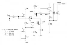
Vldimir, if you really need that much gain, the sch. from post #13 will work all right. The Zout would be dynamic impedance of CCS (T4, T5) paralleled with buffer's load and lowered by factor of NFB - all in all, about 30-50 R.
Vldimir, if you really need that much gain, the sch. from post #13 will work all right. The Zout would be dynamic impedance of CCS (T4, T5) paralleled with buffer's load and lowered by factor of NFB - all in all, about 30-50 R.
Thanks, that is not bad, could serve even as a transconductance amp for Fostex and Lowter. The potentiometer in the NFB stands for volume control from 0 to 20dB, at low volumes the NFB factor will approach 40-60dB. I aim this schematic as a pre for a follower amp (FirstWatt F4, Cuiffolli etc.). While the buffer preamp with unity gain will be OK for most of other Zens and FirstWatts.
Juma, could you advise requirements for SE output trafo, if CCS to be substituted by trafo in this schematics? It seems Papa moves to tube ideas.
Sorry Vladimir, other guys will have to answer that - I really don't think that trafos belong in signal path 😉
Sorry Vladimir, other guys will have to answer that - I really don't think that trafos belong in signal path 😉
where is da silly tongue smiley when man need it

anyway - nice xformer for ~200mA Iq is not preamp finesse territory .
I'll use choke in that position , with inductive impedance at 10Hz at least same as Ri of active element ;
same criteria for output xformer primary
silly sand boyz .....

... anyway - nice xformer for ~200mA Iq is not preamp finesse territory .
I'll use choke in that position , with inductive impedance at 10Hz at least same as Ri of active element ;
same criteria for output xformer primary
silly sand boyz .....
Ri is nearly 62 ohms at the working point, so we need 62ohms/6,28*10Hz = 1H air core choke of copper wire. Which diameter? The more the better (joke). I guess d=0,35mm could fit (need to calculate its resistance and weight).
I have got the following estimates for the air core choke:
d=0,35mm wire, L=890m, R=200 ohms
d=0,5mm L=1050m, R=107 ohms
d=1mm L=1390m, R=32,7 ohms
Which R is reasonable for the choke?
Last edited:
- Status
- Not open for further replies.
- Home
- Amplifiers
- Pass Labs
- Buffer Preamp with Shunt PS