so if i get it right, i just take a +15 supply and plug it into avcc left and right( each via a 390r 1/2 W resistor)?
i guess this is valid for buffalo 1.2 also?
i guess this is valid for buffalo 1.2 also?
For the older buffalo (not Buffalo 32S)
I would just use the ~ 7V supply you use for VA. You will need to recalculate the R.
100 ohms should be fine.
If you use some other voltage for VA, then calculate the two Rs (one to each AVCC) for ~35ma into VA - 3.3V each. 🙂
Its the current that matters here. Use the resistor or other CCS that will get you in the right range.
Last edited:
ok
but the 7V psu feeds both at the same time: avcc and VA for the older bufflao right?
but the 7V psu feeds both at the same time: avcc and VA for the older bufflao right?
Last edited:
Thanks Russ,Now Grab a metal film 390R 1/2W resistor.
Connect one end to +15V and the other to AVCC(at the bypass cap).
Cheers!
Russ
That is certainly a simple and cheap tweak to try out.
Nic
Now Grab a metal film 390R 1/2W resistor.
Connect one end to +15V and the other to AVCC(at the bypass cap).
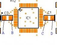
Sorry for the newbie question, but which caps are the AVCC bypass caps?
C1 and C2 on Buffalo 32S
Thank you. So I should just simply connect one end to the VA+ terminal, and the other to the positive side of C1/C2?
I'm fairly new to DIY, please bear with me 😱
Thank you. So I should just simply connect one end to the VA+ terminal, and the other to the positive side of C1/C2?
I'm fairly new to DIY, please bear with me 😱
Thats what I understood, but I guess you should stay away from the tweak if you are not sure that your skills are up to it (you will have to solder quite close to the ESS chip). Maybe wait a bit and see if others do it and report benefit.
Remember also that Russ clearly said that there will be no support for tweaking!
Remember also that Russ clearly said that there will be no support for tweaking!
Support in this case meaning repair/replacement, etc.
You now have a good constant current source feeding the AVCC input just a tad more than it really needs, which the opamp will nicely dispose of the excess to keep at the reference voltage(3.3VDC). The opamp on AVCC now is a shunt element, or rather the combination is a whole local shunt regulator. The opamp is also now having to do a lot less work, making it work better.
Sounds like a good idea. The most of the heat from regulation would now be in the resistor instead of the opamp chip package.
Have you looked at the AVCC during power-up and turn-off? If AVCC was allowed to rise past 4V it could damage the ESS chip. I believe that long, long ago Dustin said that AVCC would be OK up to about 4V or so.
If by some wierd turn of events at power-up, the op-amp wasn't able to regulate right away, or the + rail came up before the - rail, it could be bad for the silicon. 😱
I suppose it could be verified with a 'scope and you watched it closely for a few power cycles.
I think that would mostly likely only occur with a very slow-rise supply. It is something to watch out for. The opamp will be very fast to regulate under most circumstances. There are some very slow supplies out there however. It would be a good thing to check before doing the mod.
If you use the same rail as the opamp the resistor can't supply enough current to be dangerous until well after the opamp is actively working.
Its is true that your negative rail needs to have some voltage, but if it lags enough to cause an issue you should use a better power supply. 🙂
You won't have any trouble with a stock LCBPS, or Placid BP.
Yes I have verified this.
Its is true that your negative rail needs to have some voltage, but if it lags enough to cause an issue you should use a better power supply. 🙂
You won't have any trouble with a stock LCBPS, or Placid BP.
Yes I have verified this.
Last edited:
Active current source?
I dunno. That may be overkill. There is already an active device in the circuit. The op-amp.
A resistor is simple, cheap and slow.
Listening tests will now be needed 😀
Active current source?
Sure a CCD or just about any active current source will work fine, so long as its using the same rail as the opamp.
I dunno. That may be overkill. There is already an active device in the circuit. The op-amp.
A resistor is simple, cheap and slow.
Listening tests will now be needed 😀
You are right about this as long as the positive rail is well regulated the resistor is in effect a constant current source.
Here is another tip. If you are worried, or just want to be extra careful, you can use something like a 3.6V or 4V zener diode to protect AVCC.
Russ, question
Quote:
"Grab a metal film 390R 1/2W resistor.
Connect one end to +15V and the other to AVCC(at the bypass cap)."
Connect the resistor from the V+15 to "A" or "B" and "C" or "D" ?
Quote:
"Grab a metal film 390R 1/2W resistor.
Connect one end to +15V and the other to AVCC(at the bypass cap)."
Connect the resistor from the V+15 to "A" or "B" and "C" or "D" ?
Attachments
Last edited:
- Status
- Not open for further replies.
- Home
- Source & Line
- Digital Line Level
- Buffalo Tweaking