jkeny said:Your quotes above show you rowing in with Russ to say that this effort is pretty useless - do I have to spell it out for you?
I'm aware of my view that your particular proposed implementation is a fool's endeavour - using a generic board with long traces and barely any chance of local decoupling. That does not extend to all implementations of the idea of using batteries and no regulators - just to your proposed way of doing it. Any clearer now?
So now you want to find out all about the batteries I'm using - I don't think so!
Nor do I think so. I did not ask for 'all about the batteries you're using' rather I'm curious how you're going to reach the voltages you need with only batteries and no regulation.
Ask Russ, I'm sure he knows all there is to know about these DACs and how to power them!
Russ'll be able to see as well as I that that's not what I'm curious about. How exactly is Russ going to answer the question 'What's jkeny's proposed solution for getting to 3.3V with only batteries and no regs?' ? You think he's Mystic Meg? It would certainly explain why you think he can't design power supplies.
Edit: Hint be a bit more mannerly & show him some respect when asking the question as he gets a bit prickly, you know!
It might be that Russ's alleged 'prickliness' is a result of your taking the mick and siding with those from 'another place'. I very much doubt he'll give me that treatment as I haven't tried putting him down (yet). Your own private fantasies have come up with 'animosity' and 'patronisation' on this thread so its no stretch to believe you've fabricated much of the 'prickliness' you've felt. Your repeated claims to be 'open minded' look to be similarly unfounded given the way you've been ducking and diving rather than answer a simple question...
jkeny said:I'm not bothered answering you - go back to the sycophant pool from which you emerged!
What makes you think this is about me? I'll just wait around long enough for you to post up your schematics as you're not forthcoming with simple questions. 'sycophant pool' would be yet another of your private fantasies - nowt more to say on that.
For 3.3v batteries look at LiFePO4 batteries from A123 Systems, I and others use these to power supplies on computers (look for cMP and cPlay). With careful management you can keep these at, or near, 3.3v.
They are used a lot by radio-controlled-plane enthusiasts.
If I could design DACs as well (or better) than Russ then I would start my own business.
They are used a lot by radio-controlled-plane enthusiasts.
If I could design DACs as well (or better) than Russ then I would start my own business.
I think the batteries from A123 are what he is planning to use. I think the trick will be keeping the different pins at the same voltage from different batteries without vregs. Well, one of the tricks.
Brian,
In the pc there is a 3.3v supply for the Soundcard (usually a juli@) and a separate 3.3v supply for the motherboard - as they do not interact it does not matter if one is 3.4 and the other 3.2.
Alan🙂 🙂
In the pc there is a 3.3v supply for the Soundcard (usually a juli@) and a separate 3.3v supply for the motherboard - as they do not interact it does not matter if one is 3.4 and the other 3.2.
Alan🙂 🙂
Thanks Brian, Alan for the heads up on this, I wasn't aware of this technology before. I went over to A123's site - one of the cells they have on there has a brief datasheet - it does indeed look as though it stays between 3.6V and 3.0V over its useful discharge. Bet they're not cheap as it looks like single source, proprietary tech.
What would scare me shitless about powering an expensive DAC chip with these brutes is managing start-up. The internal resistance is of the order 10mohms. Suddenly connecting a battery of this kind to a bank of decoupling caps is gonna generate a pretty hefty current pulse, with the inductance of the supply wires there's the strong potential for spiking and even driving the chip into latch-up without a lot of care. I would probably choose to put some series pass transistors in the way in an attempt to slow down the turn on spike, but once they're there they might as well be regulators...
What would scare me shitless about powering an expensive DAC chip with these brutes is managing start-up. The internal resistance is of the order 10mohms. Suddenly connecting a battery of this kind to a bank of decoupling caps is gonna generate a pretty hefty current pulse, with the inductance of the supply wires there's the strong potential for spiking and even driving the chip into latch-up without a lot of care. I would probably choose to put some series pass transistors in the way in an attempt to slow down the turn on spike, but once they're there they might as well be regulators...
A123 cells
You can buy A123's from several sources. Dewalt uses the 2300mah cells in there 36V power tools there are ten cells in a pack like this.
http://cgi.ebay.com/Dewalt-DC9360-3...trkparms=65:12|66:2|39:1|72:1205|293:1|294:50
Here is some more info:
http://www.slkelectronics.com/DeWalt/index.htm
Prices for individual cells run from $10 to $20 per cell from retailers.
There are 2 sizes 1100mah and the more common 2300mah cells.
Mark
UnderstoodBrianDonegan said:Oh, I meant the various supply pins for the ESS chip.
🙂
Alan
Jkeny, I am pleased with your idea or the guy at audio consulting, whoever first suggested it. I thought of this idea a while back because of need, not want. I planned on running the house I am building on batteries, thermo-electric heat, hydro, and maybe solar 12v DC. I am a poor SCUBA instructor that fell in love in and with Thailand. I have very limited funds to build my house there and AC is going to be expensive. I thought it would be sound close if not better to the other option, $600 worth of shunt regs. Also, I would have to spend more than my house is worth just to get mains there anyway and generators are out of the question as I simply cannot afford either of these. The two choices I have are, all battery and all battery with an inverter. I will have at least a small inverter for small appliances but was not prepared to spend a lot on it. The one thing I need an inverter in the audio chain is the FirstWatt amp. If I was to run this off batteries I would need a lot of batteries and somehow build a +/-24V power supply for it. The 24V Aikido is a cinch, the PC is too(DC SMPS, and maybe a batteries to power the Juli@).
So the problem I have is the powered I/V stage on board the Buffalo32S and the Firstwatt Amps. A tweaker's board would help me out as all I need is the chip soldered to a board with solder points out. This way I can use voltage out and run the entire headphone system off batteries. The amps might have to get changed out for chip amps unless someone has a great idea how to power FW amp off batt. If I may be so bold as to agree with the TP guys at this time and say that Jkeny's board is a good idea, but it will not be optimal. The TP design is a TP design and I hope they hurry as I know it will work. What about 3D? Does everyone think flat?
Someone who knows how please build me a board quick! I like the looks of the TP one, with a couple of suggestions... This is what I need:
-A Sabre32 DAC chip soldered to a 2-layer PCB with short traces for the important leads and longer ones for the control stuff laid out all nice.
-It needs a clock
-It needs room for caps or the SMD cap pads can be next to the holes or can be on top the holes. Tweakers will want to use different caps. It needs room for through hole caps that can be mounted on top and bottom so they will fit. In fact, all should be through hole aka "John Broskie's and Peter Daniel's boards" to accomodate a few cap sizes with SMD pads aside the first holes. The chip should be the only permanent device.
-The resistors need more than one hole size, aka Broskie
-Since the majority will use this in stereo there should be a jumper system to shorten the traces for two channel mode.
If this is done, I think you will please everyone.,, Mostly everyone. The TP layout is as close to what I want with the need for holes for caps.
Still working on this but I'm doing a TAS1020B (48LQFP) USB receiver first on protoboard to try out some ideas and avoid mistakes on an expensive Sabre DAC.
So far it has proven easy to put 0.1uF C0G PS decoupling smd caps on each supply pin (through hole caps are not recommended here) as close to the PS/Gnd pins as I want (within a couple of milimeters - the limit being the soldering iron tip width - I'll post some pics if there's interest). There's still through holes & pads for caps/connectors further away from the chip
So far it has proven easy to put 0.1uF C0G PS decoupling smd caps on each supply pin (through hole caps are not recommended here) as close to the PS/Gnd pins as I want (within a couple of milimeters - the limit being the soldering iron tip width - I'll post some pics if there's interest). There's still through holes & pads for caps/connectors further away from the chip
Why use C0G for decoupling? sounds like overkill to me. if you go for something like X5R you'll need to roughly double the value to make up for the lousy voltage-capacitance coefficient but the physical size is so much smaller that the series inductance will be lower.
Yes, It's late here & I'm tired - meant to say I used X5R - would have used C0G for their higher stability but size & cost were offputting.
Why would stability be desirable for a decoupling application?
Remember that if you want 0.1uF effective, then depending on the working voltage of your cap, you need to choose something considerably bigger as the capacitance of X5R droops with DC bias applied.
Remember that if you want 0.1uF effective, then depending on the working voltage of your cap, you need to choose something considerably bigger as the capacitance of X5R droops with DC bias applied.
That's effectively what 'stability' means. So it don't shed any light on why you want less variations under dynamic conditions in this particular application.
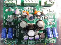
hybride said:Buffalo 1.2 ;-)
The change of caps near the Sabre chip has a relative big influence on the sonics.
Can you give us a description of what you've done. and the changes you heard?
Ok, Had good results with bypassing caps on the Buffalo24. So with the B32 i went to Mattijs de Vries from Triple M audio for advise. He is real expert and designer of power supply's for audio circuits. He never uses ceramic cap's in analog stages of the circuit because they sound bad. He also dislikes Oscons for analog stages. Oscons are very good, but there are 'better sounding' caps. What i did is remove the ceramic decoupling caps near the Sabre chip and change them for what he advised me. I have to ask him, but i thought that the orange ones are silver-mica and a little quality elco 4,7uf. I changed the analog Oscons for Philps elco's (NOS). For the 3 voltages near the clock (i suppose for the digital part) paralleled 3 x Panasonic FM elco.
Result: more open and dynamics top, more overall control. Less 'dull', more sparkling.
Next tip ;-)
I feed the B32s with batteries. Mattijs told me that feeding equipment directly from batteries gives worse results, even with good capacitors as direct buffer. Reason is that batteries has bad AC impedance characteristics. They where made for DC. When putting low esr elco's parallel it's only getting worser because they will influence with the accu. The result is worse damping. The solution is to feed equipment directly from a big elco with a serial resistor. So from the batterie with a 1-10 ohm resistor to one high capacity elco (44000 uf or higher) With that, there will be a RC filter. With the formula F=1:2*pi*RC the rollover frequency can be calculated. In other words; above the rollover frequency all the current will be taken out of the elco, while the batterie is loading the elco with straight DC current.
The values depend on the current. The lower the current the lower capacitors can be used.
- Status
- Not open for further replies.
- Home
- Source & Line
- Digital Line Level
- Buffalo Tweaking