No - you need to use one or the other. The simplest solution if you wish to use an external clock is to not install the supply for the clock (trident).
I forgot what clock you are using, but doesn't the 957 have a hi z disable pin? It would seem straight forward to implement that feature as a DIY- simply place a grounding switch flip-flop between disables. One would have to swap out clocks however.
They clock we are using does not have a disable pin, but if it is not powered the output is hi z. 🙂
Plus if you don't plan on using the on board clock you likely also don't want a shunt reg consuming current it is not using.
The bottom line is if you are going external - you need to commit to that. 🙂
The bottom line is if you are going external - you need to commit to that. 🙂
Not really a Buffalo question bit it is related...
I'm building a Buffalo SE with Placid HD and Placid HD BiPolar
Started with the Placid HD BP. Manual says about the trimmers: Measure resistance between the two outer pins. (pin 1 and 3 in my picture).
I have don that but the resistance does not change. (stays 9.5K). Trimmer is not installed on the PCB. What am I doing wrong here?
Attachments
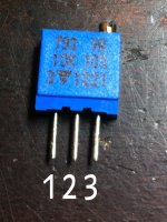
That is because pin 2 is the wiper.. pin 1 and 2 are the far ends of the pot plane, and does because of that have a constant resistance.
You will notice on the board, the wiper pin (2) is shorted to one of the outer pins, which is why you will see adjustment once it is installed.
On my...
very slowly progressing (in no hurray, as I am waiting for the new TPA USB interface to complete the project) B-IIIse build I went ahead and installed a low profile socket for the oscillator Trident on the board. This DAC will be built up first on MDF for fine tuning and proof of concept, so I can easily listen in both synchronous and asynchronous modes. With B-II right now I am almost certain I prefer synchronous clocking, but being able to make easy comparisons should help me to be sure.
I must say, it is tempting to go with async operation, just because of the higher flexibility this offers. I just finished upgrading a DAC I built for friend with the B-IIIse board/new Tridents, and set him up with an I2S input (via an LVDS/HDMI board from K&K audio) and SPDIF, with a simple rotary switch for input select on the front panel. I must say the B-IIIse provides a simple and elegant solution for those wanting an I2S and SPDIF input.
I apologize if this has been asked. I read the manual. But it wasn't clear, can I turn off the on board I2C controller and "plug in" a different one (i.e. arudino, etc) later on when I had the time ?
No, you can't turn off the on-board firmware. You need to remove it from the socket. See the paragraph "Using external I2C controllers".
I have connected the volume control pot (supplied10k) and it's working ok,
but I would like to be able to use a bigger part of the turn. As it's now I'm
bearly using a quarter turn. Full volume is really loud and half turn almost silent.
Any ideas, maybe a 5k pot ? Is there 10k two turn pot's ?
It's for the B III se
but I would like to be able to use a bigger part of the turn. As it's now I'm
bearly using a quarter turn. Full volume is really loud and half turn almost silent.
Any ideas, maybe a 5k pot ? Is there 10k two turn pot's ?
It's for the B III se
The value of the pot won't make any difference.
The pot just forms a voltage reference which is read by an ADC. It is the DAC itself that does the attenuation digitally.
The attenuation is a linear progession (as the pot is linear) from 0db to -63.5db - but note that decibels are a logarithmic scale. 🙂
To change the range would require custom firmware, or an external way to manipulate the reference voltage. 🙂
You could also perhaps use an anti-log pot and/or adjust the output level of the output stage.
Last edited:
The value of the pot won't make any difference.
The pot just forms a voltage reference which is read by an ADC. It is the DAC itself that does the attenuation digitally.
The attenuation is a linear progession (as the pot is linear) from 0db to -63.5db - but note that decibels are a logarithmic scale. 🙂
To change the range would require custom firmware, or an external way to manipulate the reference voltage. 🙂
You could also perhaps use an anti-log pot and/or adjust the output level of the output stage.
Thanks, maybe I will go for some (sort of) gearbox solution.
A multiturn linear 10k pot would work right ?
This one maybe http://se.farnell.com/eti-systems/mw22b-3-10k/potentiometer-3-turn-10k-ohm-0/dp/1307124
Last edited:
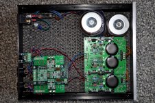
I finally finished by Buffalo-IIISE. The enclosure is really too small (11.6" x 9.5" x 2.5" inside dims) for good separation between the analog boards and the power supplies, but the hum levels are far below audibility. Good enough.
Attachments

Thanks, maybe I will go for some (sort of) gearbox solution.
A multiturn linear 10k pot would work right ?
This one maybe MW22B-3-10K - ETI SYSTEMS - POTENTIOMETER, 3 TURN 10K OHM | Farnell Sverige
Reverse-log pots are not common, but you could use a (normal) log taper pot and hook it up backwards. Just remember that CCW increases volume. 🙂
Alternatively, you could add an external resistor in series with the ground end of your existing linear-taper pot. This prevents from turning the volume all the way down, but that might not be a problem. If you use a 10k resistor with your 10k pot then your volume at max CCW will be what it is now at 50%.
Cheers,
Dave.
Another alternative is a resistor in parallel between the wiper and one end of a linear pot as shown in this article: Potentiometers (Beginners' Guide to Pots)
Reverse-log pots are not common, but you could use a (normal) log taper pot and hook it up backwards. Just remember that CCW increases volume. 🙂
Alternatively, you could add an external resistor in series with the ground end of your existing linear-taper pot. This prevents from turning the volume all the way down, but that might not be a problem. If you use a 10k resistor with your 10k pot then your volume at max CCW will be what it is now at 50%.
Cheers,
Dave.
Oops, yes you are correct. A law-faking resistor would need to be attached from +3.3VDC to the wiper in this case to yield the correction dahlberg is looking for.
Sorry about that.
Cheers,
Dave.
Sorry about that.
Cheers,
Dave.
- Status
- Not open for further replies.
- Home
- More Vendors...
- Twisted Pear
- Buffalo III - SE