Hi Joe,
It makes little difference the voltage at the end of the impedance.
The problem is not one of offset but of modulation.
So the answer is yes? I can use two 1R resistors across the combined outputs (195R) and ground the junction between the two 1R? The output would be in the mV AC range but easily upped to 2V by an extremely low noise no GFB diff amp.
Deliberately creating an 8mA DC current offset will not bother the DAC?
This has got me intrigued.
Cheers, Joe
The DAC does not care what voltage it sees from 0V to AVCC. It is a voltage source with an output impedance of 195R. nothing more nothing less. It only acts like a current source if you treat it like one.
Remember an ideal current source looks like an infinitely high impedance to the load.
It makes absolutely no difference to the DAC what the bias voltage is, now to the final result it can make a world of difference what the bias voltage is, and if I were not using feedback I would not go into 0V(GND) (and I would go into 0V only if you use super symmetrical feedback) if it can be avoided. You would do much better to make the "virtual gnd" a bias voltage of exactly AVCC/2. This is almost never really 1.65V 🙂
Cheers!
Russ
Last edited:
So the answer is yes? I can use two 1R resistors across the combined outputs (195R) and ground the junction between the two 1R? The output would be in the mV AC range but easily upped to 2V by an extremely low noise no GFB diff amp.
Deliberately creating an 8mA DC current offset will not bother the DAC?
This has got me intrigued.
Cheers, Joe
Joe,
If you are still confused the simple answer is that if I-V input is set to
Avcc/2 (1.65V) there is zero offset current to deal with. If the I-V (or
whatever analog cct you choose to use) is set to gnd, there will be an 8mA
offset current to deal with.
The choice of zero FB, opamp, full dif opamp with ref (super-sym-like) really
doesn't make much difference as long as you allow for the 8mA offset
current when set to gnd.
I'm currently using a transformer and just let DAC OP sit where it wants. It
works very well and contrary to common belief here can very well approach
the linearity of the DAC at frequencies above a few hundred Hz with the right
transformer.
Probably the best sound subjectively will be a toss between a good
transformer and a very carefully implemented current conveyor such as
grounded base stage. The problem with Sabre is very low OP Z (195R) and
very high current swing (+-8mA / phase) This makes it difficult to realise
a very linear 0 FB CCT without some form of local FB - although it is
possible.
cheers
Terry
Last edited:
JProbably the best sound objectively will be a toss between a good
transformer and a very carefully implemented current conveyor such as
grounded base stage. The problem with Sabre is very low OP Z (195R) and
very high current swing (+-8mA / phase) This makes it difficult to realise
a very linear 0 FB CCT without some form of local FB - although it is
possible.
cheers
Terry
Not so much a problem, but a challenge. 🙂
I have tried transformers, and have no problem telling you I think they sound great. An maybe even some have heard things even better than what I have heard so far. Still I am not sold. Can I be? Perhaps... I have not heard every transformer out there yet. 🙂
I have also tried (As can be surmised from my posts about Legato) the grounded base solution and found it incredibly awesome. Especially when the ground is virtual and AVCC/2 🙂
Cheers!
Russ
Joe,
If you are still confused the simple answer is that if I-V input is set to
Avcc/2 (1.65V) there is zero offset current to deal with. If the I-V (or
whatever analog cct you choose to use) is set to gnd, there will be an 8mA
offset current to deal with.
The currrent from both phases will be plus 8mA, so if grounded, the answer to "there will be 8mA offset current to deal with" is that it will go back through the power supply. That takes care of that, anything else to worry about?
I well understand the other techniques and indeed grounded base sitting on 1.65V would be the ticket. But this is not what I am asking questions about.
But Terry, you know what I am getting at. Using "diamond transistor" I want the "+" from the DAC to goto high Z "base" which is positive and I want "-" from the DAC to goto low Z "emitter" which is of course negative input. The "diamond transistor" does not have identical/symmetrical input Zs, indeed the "-" emitter sits somewhere between 50R and 100R. That Z is not a problem provided that R to ground is say 1 Ohm and likewise from the high Z "+" input will also have 1R to ground. It will be symmetrical despite the different input Zs.
OK, I could find a way to float it on circa 1.65V and hence no offset current. Indeed have done this with AD1955 for example. But that leaves me with 1.65V further down the line and a likely coupling cap. I'd like to avoid that headache.
But with the arrangement I have in mind, yes it will create offset current(s), but they will have a natural path to follow.
Again, my simple question is, not what other options there are, but whether this option will work?
If it does, the answer is yes. We can then go to the next step and find out just how good it will be, even discuss how we may think it will do. But I just want to get past that first step.
But I am with you guys that grounded base would be the best way, and indeed I will also try transformer - a QuadFilar 1:1 that I reckon may well be near perfection. 🙂
Let the fun commense....
Cheers, Joe
Last edited:
I well understand the other techniques and indeed grounded base sitting on 1.65V would be the ticket. But this is not what I am asking questions about.
Again, my simple question is, not what other options there are, but whether this option will work?
If it does, the answer is yes. We can then go to the next step and find out just how good it will be, even discuss how we may think it will do. But I just want to get past that first step.
But I am with you guys that grounded base would be the best way, and indeed I will also try transformer - a QuadFilar 1:1 that I reckon may well be near perfection.
Cheers, Joe
*I* have already gone down that road (Diamond transistor), and after testing it thoroughly we rejected the idea because it simply does not work as well as the other things we have tried. There is an excellent reason for this. Presenting the DAC with an asymmetrical load is *far* worse then using it in voltage mode. Your just asking for higher IMD and THD when you do that. Avoid this like the plague. Of course, this type of approach *can* work, and even work well, just not *as well* as the other things we have done. 🙂
I would hope you know enough to move on with your own idea. If so I have already given you all of the information you could possibly need to answer your own questions. What are you waiting for? There is nothing new to tell you about the way the DAC works in terms of the outputs.
I won't try it for you now -
 - You are going to have to do some legwork yourself here.
  Only you can answer if your solution will work, as it will be entirely your own. 🙂 What I have already told you is more than enough to get that done.
You would probably be better off just to use the DAC as a voltage source into your "near perfect" transformer than to pursue the other ideas you have mentioned. 😀
Anyway best of luck.
Cheers!
Russ
I won't try it for you now -
I wasn't suggesting that and... yes I have tried it before with DACs that already have only a current offset but not voltage offset. It works rather well - that is it does to the ear and that after all is the final arbiter. 😉
You would probably be better off just to use the DAC as a voltage source into your "near perfect" transformer
I'll do that too and then have a valid comparison that should prove interesting. Also try floating it on 1.65V and no current offset but use a coupling cap. Re the transformer I have in mind, alas "near perfect" is not perfect but sometimes some things just about seems the perfect answer, if you know what I mean. That was the context anyway.
Cheers, Joe
PS: BTW, it will not be an asymetrical load as you suggest.
Last edited:
There is an excellent reason for this. Presenting the DAC with an asymmetrical load is *far* worse then using it in voltage mode. Your just asking for higher IMD and THD when you do that. Avoid this like the plague.
I did not suggest an asymmetrical load. Indeed I did say:
"It will be symmetrical despite the different input Zs."
The only asymmetry there will be is that of the DAC itself as the load it will see per phase is the same. On the "-" input which is in the order of 50-100R will see 1R in parallel and hence the 1R will dominate. The 1R on the "+" input will not be modified as it is high Z.
Cheers, Joe
Last edited:
You will need to show me how two voltage sources with the same output impedance into two different load impedance's can be symmetrical. 🙂
They are two different loads on the same output channel. That in itself cannot be symmetrical. 🙂
Now if you alter the impedance of one end based on feedback from the other, then you are no longer talking about zero global feedback.
They are two different loads on the same output channel. That in itself cannot be symmetrical. 🙂
Now if you alter the impedance of one end based on feedback from the other, then you are no longer talking about zero global feedback.
They are two different loads on the same output channel. That in itself cannot be symmetrical. 🙂
.
Hi Russ
I just edited my post above to answer that. The load will be symmetrical.
Cheers, Joe
You really then do not have different input Zs. The input Z is the *load*. Your are setting the input Z by using the extra resistor(s). The impedance into the node after the resistor setting the load is irrelevant to the discussion.
Is transformer on output for the DAC, feeding the analogue stage does necessarily operates the DAC as a voltage source?
Legato with dual mono Buf2:s?
Dear Russ,
will the Legato work with two Buffalo2:s running in dual mono, ie with 32mAp-p current swing?
and no coupling caps, right?
Regards,
Dear Russ,
will the Legato work with two Buffalo2:s running in dual mono, ie with 32mAp-p current swing?
and no coupling caps, right?
Regards,
Is transformer on output for the DAC, feeding the analogue stage does necessarily operates the DAC as a voltage source?
Hi,
Yes it certainly could handle that current swing, but you would want to change a couple parts. Honestly, I would not do it. You could actually get a bit worse THD in this case. Instead I would do what we do with the IVY-III
It (like the D1 etc) is AC coupled, but it could also be transformer coupled, or even DC coupled in some situations.
I am currently using 100uf Silmic II for coupling, and am quite happy with them. We are also looking at the new Nichicon silk caps (I forget the model at the moment).
Legato aims for simplicity. It is a D1 style common base I/V stage.
Counterpoint II is different. It uses a folded cascode and servo to eliminate offset, but it is quite a lot more complex circuit. It may still be offered at some point.
Cheers!
Russ
Last edited:

Is transformer on output for the DAC, feeding the analogue stage does necessarily operates the DAC as a voltage source?
Yes.
Hi,
Yes it certainly could handle that current swing, but you would want to change a couple parts. Honestly, I would not do it. You could actually get a bit worse THD in this case. Instead I would do what we do with the IVY-III
It (like the D1 etc) is AC coupled, but it could also be transformer coupled, or even DC coupled in some situations.
I am currently using 100uf Silmic II for coupling, and am quite happy with them. We are also looking at the new Nichicon silk caps (I forget the model at the moment).
Legato aims for simplicity. It is a D1 style common base I/V stage.
Counterpoint II is different. It uses a folded cascode and servo to eliminate offset, but it is quite a lot more complex circuit. It may still be offered at some point.
Cheers!
Russ
What is the minimum recommended size for the coupling cap?
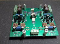
Here is the Legato.
I am really enjoying it.
When do you think we might enjoy it? 🙂🙂🙂
Choosing the cap will depend on your load. I would not go less than about 10uf (8hz corner) if you are using the on-board bal/se converter as it will present a 2K load.
100uf should suite just about anything. I have even used it driving my HD650 headphones. 🙂
100uf should suite just about anything. I have even used it driving my HD650 headphones. 🙂
- Status
- Not open for further replies.
- Home
- More Vendors...
- Twisted Pear
- Buffalo II