Can you post some pictures of the transistors on the Placid? I am thinking you have something in the wrong spot, so pics should show labels if possible.
Hi glt,
I had a 5w 15ohm resistor in my parts kit. I placed it across output of placid and voltage was steady at 5.5. As suggested that resistor got very hot in few minutes.
Per Russ's suggestion,I measured the resistances across the caps in AVcc module-
C1 measured at 18k and C2 was in megaohm range. I hope measured the right ones.
Brian,
I will try to get the pictures of the transistors on placid. If I don't get clear pictures, is it OK to post the numbers on the devices?
Thanks for all the help guys, I hope I will get it up and running soon
Suresh
I wasn't talking about the AVCC module, I meant on the DAC itself.
There should be no shorts registered across any of the caps at all.
There should be no shorts registered across any of the caps at all.
Hi,
Can you check the power supply voltage without any connection. You found that the resistance of the Buffalo was 15k. Sometime the LM78xx do not put voltage out on less there is a load. Since the resistance is 15k and dividing 5.5 volts/15K this give you a low load. Or you can put the resistor in parallel with the Preamp and see what happen.
Can you check the power supply voltage without any connection. You found that the resistance of the Buffalo was 15k. Sometime the LM78xx do not put voltage out on less there is a load. Since the resistance is 15k and dividing 5.5 volts/15K this give you a low load. Or you can put the resistor in parallel with the Preamp and see what happen.
Hi,
Can you check the power supply voltage without any connection. You found that the resistance of the Buffalo was 15k. Sometime the LM78xx do not put voltage out on less there is a load. Since the resistance is 15k and dividing 5.5 volts/15K this give you a low load. Or you can put the resistor in parallel with the Preamp and see what happen.
There are no LM78xx regulators involved
Hi,
Oppss Still some power supply require a load to operate. Do the test with the resistor connected to the preamp. Check the output voltage.
Oppss Still some power supply require a load to operate. Do the test with the resistor connected to the preamp. Check the output voltage.
Hi glt,
I had a 5w 15ohm resistor in my parts kit. I placed it across output of placid and voltage was steady at 5.5. As suggested that resistor got very hot in few minutes.
...
Suresh
That means it is almost certain the Placid is not at fault. That is how I built my Placid. After completing it, I let it sit with a resistor for many hours to make sure the supply is solid.
Try lowering the voltage of the Placid to 5V or even 4.5V. The opamp of the AVCC supply specs out at around 5.5V (if I remember correctly)
Last edited:
Was the Buffalo initially powered with more than 5.5V, say during testing of the Placid? A cooked AVCC may be causing the short. Try powering the Buffalo without the AVCC module in place and see if you get the Mute led to light.
Removed the AVCC module and tried powering up, none of the leds lighted up.
I was very careful on adjusting placid per instructions on initial power up as the instructions are explicit the voltage on power up can exceed 5.5 easily.
I tried adding the loading resistor per another suggestion but the problem remains
I was very careful on adjusting placid per instructions on initial power up as the instructions are explicit the voltage on power up can exceed 5.5 easily.
I tried adding the loading resistor per another suggestion but the problem remains
The key is you need to adjust the Placid voltage before you connect it to the DAC(or any other load), not while it is connected to the DAC.
The DAC will not lock if the AVCC module is damaged.
The DAC will not lock if the AVCC module is damaged.
Hello Russ,
Placid was adjusted with buffalo board not connected to give 5.45v. As per glt's suggestion tried the resistor load instead of dac and placid holds the voltage steady at 5.45v with 15 ohm resistor load.
LEDS are placed in socket holders as I intended them mount on the front panel of the dac case. I removed and connected them to battery supply with resistor and they work fine.
I have a Salas shunt board that puts out 5v at 200ma designed for the digital section of the TDA 1541 dac and I have tested it on my TDA1541 Dac.Can I use it to power the buffalo board and see whether it works?
It probably won't be enough current.
There are pads for three headers next to each VREG on the Buffalo II.
Check the impedance of each of the outside pins of those headers to GND in the middle of those headers with the DAC powered off.
There are pads for three headers next to each VREG on the Buffalo II.
Check the impedance of each of the outside pins of those headers to GND in the middle of those headers with the DAC powered off.
Last edited:
Here are the values -
Central one near the C10 cap 9.2K
One near the right output header and C11 cap 6 K
One near the Left output header and C18 cap 0 ohms
Central one near the C10 cap 9.2K
One near the right output header and C11 cap 6 K
One near the Left output header and C18 cap 0 ohms
There are two labeled pads you should be measuring to GND at each of those headers. You need to indicate which pad you took each measurement from.
Lets try this again
Header near c10 cap
Vdd-xo to G - 9k
Vd to G- 17Mohm
header near cap C11
Dvcc to g - 4k
Vd to g- 17 Mohm
Header near cap C18
Vdd to G- zero ohm, multimeter reads continuity
Vd to G- 17Mohm
Hope that is helpful
Header near c10 cap
Vdd-xo to G - 9k
Vd to G- 17Mohm
header near cap C11
Dvcc to g - 4k
Vd to g- 17 Mohm
Header near cap C18
Vdd to G- zero ohm, multimeter reads continuity
Vd to G- 17Mohm
Hope that is helpful
Yes, very helpful.
The problem seems to be that you have a short after or within the 1.2V VDD regulator.
This could mean a couple of things.
1) Perhaps a short between components pads. Check around C12 and C15 on the bottom of the board.
2) Could also be a ESD damaged chip.
3) Least likely is a dead VREG, I say this because the current it could ever see is limited by the Placid itself.
Also closely inspect all of the components and DAC pins connected to that net. For example C21 and C22.
Last edited:
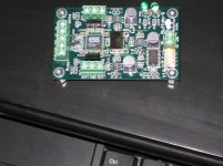
I carefully looked for any visible shorts both near the reg and Dac and under the board. Pictures attached. I could not see any problem.
Looks like the chip may be damaged or reg it self may be shorted. Unfortunately I do not have SMD capabilities. Can I send the board for repair to Twisted Pear?
Looks like the chip may be damaged or reg it self may be shorted. Unfortunately I do not have SMD capabilities. Can I send the board for repair to Twisted Pear?
Attachments
Last edited by a moderator:
Have you tried feeling the chips to see if any of them are getting hot when the buffalo is powered on? If you're loading the placid so hard that the voltage rail drops to 1.2 volts a lot of current is going somewhere.
I've had a similar problem where I blew an ASRC chip. On power on, the 3.3veg was loaded down and the ASRC chip itself got very hot. It didn't take a genius to figure out what had gone wrong.
If there is a short internal to one of the components, it might heat up also. However if it's a solder bridge somewhere they probably wont.
- Status
- Not open for further replies.
- Home
- More Vendors...
- Twisted Pear
- Buffalo II module does not power up