Hello
I purchased a buffalo 2 dac in August and a placid supply in October 2010. I finally managed to assemble the placid supply and powered it up. I get 5.5v at the output of placid with 9 v ac in . The transformer I am using is avel which is capable of supplying 1.2 amp
When I connect the power supply to Buffalo, I do not see any leds lighting up on the Avcc module nor spdif lock. In fact the the voltage of placid drops to 1.6 Vwith buffalo dac board connected which is what I measure at DAC power input terminal as well as AVCC input . Thinking that it could be power supply issue, I used placid to power up 5v receiver section of my other TDA 1541 dac and it worked without any problem.
Am I missing something here .I was excited about this hearing this new dac. Please help
Yes. Reads per instruction manual exactly at 0.055V across R3.
Suresh
This is measured with the Placid connected to the load?
Without load, placid output 5.45V with voltage across R8 measuring 0.35v dc and voltage across R3 0.055v
When buffalo is connected, placid output drops to 1.6v and R3 drops to 0 but voltage across R8 remains same at 0.35v Dc.
Adjusting VR1 does not bring up voltage across R3 to required specs of 0.05 and above.
When buffalo is connected, placid output drops to 1.6v and R3 drops to 0 but voltage across R8 remains same at 0.35v Dc.
Adjusting VR1 does not bring up voltage across R3 to required specs of 0.05 and above.
Yes. I looked at the pictures of other boards posted in the forum and made sure the in, ground and out are correctly oriented on the AVCC module and the main board
Look for simple mistakes. The "short" idea os good. Check all your solder joints and make sure you have no bridges.
Also check other components, like the diodes, that are easily reversed. I found out I had put a diode in backwards on the placid and it worked, but not at the correct voltage/current until I fixed it.
Check both the placid and buffalo boards.
Also check other components, like the diodes, that are easily reversed. I found out I had put a diode in backwards on the placid and it worked, but not at the correct voltage/current until I fixed it.
Check both the placid and buffalo boards.
Double checked placid parts .All OK
Went over both boards with magnifying glass. Nothing wrong that I could see.
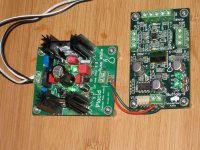
Attached are some pictures of the assembly
Went over both boards with magnifying glass. Nothing wrong that I could see.
Attached are some pictures of the assembly
Attachments
Last edited by a moderator:
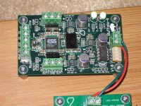
Thanks for the reply. Is it the socketed chip on the right? I want to be sure before I do anything silly.
Hi,
Check the resistance at the Buffalo voltage input connector to see if you have a short in the board. Low resistance reading means you have a short some place in the Buffalo board.
Check the resistance at the Buffalo voltage input connector to see if you have a short in the board. Low resistance reading means you have a short some place in the Buffalo board.
Resistance at the input connector with or without firmware chips 15kohms
Pulling the firmware chip out and reconnecting placid did not solve the problem
Pulling the firmware chip out and reconnecting placid did not solve the problem
Hi,
Try connecting a 15K resistance to the power supply without connecting it to the Buffalo board. Check the output voltage from the power supply.
Try connecting a 15K resistance to the power supply without connecting it to the Buffalo board. Check the output voltage from the power supply.
kamaths,
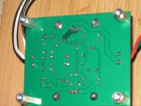
Your earlier series of pics included an underside shot of the BII board (no longer included). On the lower set of the riser pins (to the elevated power supply) there appeared to be a little soldering swarf; does that clean off by simply pushing it off? All remnants of the soldering process should be cleaned off with alcohol and a cotton-tipped swab. If the solder sticks and does not budge then it may be an unintended soldering bridge that may be part of your problem. I came back to your thread and wished to take a better look at that area but that pic no longer displays on my browser.
Hope this is some help,
Ron.
It appeared to some flux residue, I cleaned the board again especially around the pins with a cotton swab dipped in Flux Off. Unfortunately no luck.
Tauro0221 has a good idea. You want to determine if the Placid is at fault.
Operating, the Placid should provide ~400 mA at 5.5V. This means (with the equation V=IR), that a resistor of ~13 ohm should simulate your current consumption. Get a bunch of resistors together and put them in parallel with (because it will get very hot) to obtain say 15 ohm. if you put 6 100 ohm resistors in parallel, you will get 100/6=16.6 ohm and 7 resistors will be 14.3 ohm. Then connect the resistors to the output of the Placid and see what happens. If the voltages of the Placid are maintained and the resistors get hot, Then the Placid is working correctly.
Operating, the Placid should provide ~400 mA at 5.5V. This means (with the equation V=IR), that a resistor of ~13 ohm should simulate your current consumption. Get a bunch of resistors together and put them in parallel with (because it will get very hot) to obtain say 15 ohm. if you put 6 100 ohm resistors in parallel, you will get 100/6=16.6 ohm and 7 resistors will be 14.3 ohm. Then connect the resistors to the output of the Placid and see what happens. If the voltages of the Placid are maintained and the resistors get hot, Then the Placid is working correctly.
measure the resistance across the caps around the voltage regulators on the Buf-II. If there is a short somewhere on the board (even after the caps) that test should show it.
- Status
- Not open for further replies.
- Home
- More Vendors...
- Twisted Pear
- Buffalo II module does not power up