^^Very helpful, thank you.
Do you find a difference between SPDIF and I2S mode? In that case I'll get a cheap soundcard and hack it up for I2S.
Do you find a difference between SPDIF and I2S mode? In that case I'll get a cheap soundcard and hack it up for I2S.
yes i2s does sound better then spdif, better air and space between instrument, easier to listen to .
i have a few question for russ and brian:
i have the v1.1 broad with the old comparator, using i2s interface mean i dont need to upgrade the comparator?
in the buffalo schematic , the d1,d2, dck, have 47k ohm connected to ground and 22 ohm to the dac, what do those resistor for?
what's the optimal voltage signal level for the d1,d2, dck? the signal output from my emu1212 measured about 3v ac, and 1.5 v dc, is this good for the dac?
when i run 96kz i2s signal , all i can hear is pop and click what does that mean?
thanks
Here is the I2S connection for Juli@ soundcard:
20 Pin header:
Pin 1 D2
Pin 5 D1
Pin 7 DCK
10 Pin header:
Pin 6 GND
Works like charme on the Buffalo DAC, much better than spdif.
(Thanks Alfred K.)
20 Pin header:
Pin 1 D2
Pin 5 D1
Pin 7 DCK
10 Pin header:
Pin 6 GND
Works like charme on the Buffalo DAC, much better than spdif.
(Thanks Alfred K.)
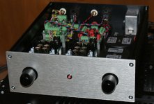
A finished Buffalo DAC
Hi,
I've been busy the last days with my Buffalo DAC. Now it's all finished and I'm very happy with the result.
All I tweaked was the Vref and I don't feel the need to go any further, it's just perfect.
If you like you can finde a couple of pics following this link:
Buffalo DAC
Cheers!
masi
Hi,
I've been busy the last days with my Buffalo DAC. Now it's all finished and I'm very happy with the result.
All I tweaked was the Vref and I don't feel the need to go any further, it's just perfect.
If you like you can finde a couple of pics following this link:
Buffalo DAC
Cheers!
masi
Attachments
Re: A finished Buffalo DAC
Wow! Very well executed DAC. Nice job!
Cheers!
Russ
masi said:Hi,
I've been busy the last days with my Buffalo DAC. Now it's all finished and I'm very happy with the result.
All I tweaked was the Vref and I don't feel the need to go any further, it's just perfect.
If you like you can finde a couple of pics following this link:
Buffalo DAC
Cheers!
masi
Wow! Very well executed DAC. Nice job!
Cheers!
Russ
Re: A finished Buffalo DAC
Hey! That's a net job. Congratulations. Did you cut and engraved the chassis by yourself or did hifi-2000 made the metal work for you? I know they offer this service.
Thanks
Gianluca
masi said:Hi,
Now it's all finished and I'm very happy with the result.
Hey! That's a net job. Congratulations. Did you cut and engraved the chassis by yourself or did hifi-2000 made the metal work for you? I know they offer this service.
Thanks
Gianluca
Thanks for the compliments. 🙂
It's a Hifi-2000 Case (Galaxy GX288) supplied from audiophonics.fr in France.
The metal work (back panel and insertion panel) comes from schaeffer-ag.de. I wasn't aware that Hifi-2000 is offering that kind of service. With these panels you really get a professional look, there's no way I could have done that myself. One blemish may be the blank outside edges but AFAIK you could have drilled and cut your own materials.
I like the Galaxy case. It looks really neat and the aluminum side profiles allowed the insertion of a mounting panel. Like that, mounting is straight forward, everything perfectly on its place.
Analog and digital signal wires are well separated from power supply and control wires which are routed underneath this panel. There’s no hum or hiss or anything like that to hear on the speakers.
So far I’m running my DAC without the top cover to please myself with the interiors - maybe I should get a transparent acryl cover. 😉
masi
last Ivy mods
I am about to complete a Buffalo/Ivy combination. I was wondering what is the final and, possibly, best configuration of IVY that is holding after all your experimentations.
In particular,
C1-4: 4.7nF or 10nF?
R17-20: jumper or 21R?
R1-4: 187R or 357R or jumper?
R5-8: jumper or 187R?
C13-16:2.2nF or 10nF?
Thanks guys.
Re: last Ivy mods
This is what I suggest.
For 2VRMS output:
1) 10nf
2) jumper
3) 187R
4) jumper
5) 10nf
For 4VRMS output:
1) 4.7nf
2) jumper
3) 357R
4) jumper
5) 10nf
Cheers!
Russ
oj said:I am about to complete a Buffalo/Ivy combination. I was wondering what is the final and, possibly, best configuration of IVY that is holding after all your experimentations.
In particular,
1) C1-4: 4.7nF or 10nF?
2) R17-20: jumper or 21R?
3) R1-4: 187R or 357R?
4) R5-8: jumper or 187R?
5) C13-16:2.2nF or 10nF?
Thanks guys.
This is what I suggest.
For 2VRMS output:
1) 10nf
2) jumper
3) 187R
4) jumper
5) 10nf
For 4VRMS output:
1) 4.7nf
2) jumper
3) 357R
4) jumper
5) 10nf
Cheers!
Russ
thanks Russ!
Just an additional question on the Buffalo. What are the following two dip switch controls: (i) notch delay and (ii) DPLL BW?
Just an additional question on the Buffalo. What are the following two dip switch controls: (i) notch delay and (ii) DPLL BW?
oj said:thanks Russ!
Just an additional question on the Buffalo. What are the following two dip switch controls: (i) notch delay and (ii) DPLL BW?
Notch delay adds a 1/64 delay to the modulator which is supposed to improve DNR slightly. 🙂
DPLL bandwidth is either LOWEST or MEDIUM. Best jitter ejection is achieved at LOWEST, but some poor quality sources will not lock (or stay locked) well with this setting. For those sources its better to use the MEDIUM setting.
Cheers!
Russ
Re: Re: last Ivy mods
It would be EXTREMELY helpful if all of these excellent nuggets of information were added to the relevant manuals and the TP website.
It is an extreme PITA to sift through these mega-threads looking for useful information.
I also find it odd that customers are not directed to the support forum on the TP site. Isn't that its intended purpose?
Otherwise, keep up the excellent work.
Russ White said:
This is what I suggest.
For 2VRMS output:
1) 10nf
2) jumper
3) 187R
4) jumper
5) 10nf
For 4VRMS output:
1) 4.7nf
2) jumper
3) 357R
4) jumper
5) 10nf
Cheers!
Russ
Russ White said:
Notch delay adds a 1/64 delay to the modulator which is supposed to improve DNR slightly. 🙂
DPLL bandwidth is either LOWEST or MEDIUM. Best jitter ejection is achieved at LOWEST, but some poor quality sources will not lock (or stay locked) well with this setting. For those sources its better to use the MEDIUM setting.
Cheers!
Russ
It would be EXTREMELY helpful if all of these excellent nuggets of information were added to the relevant manuals and the TP website.
It is an extreme PITA to sift through these mega-threads looking for useful information.
I also find it odd that customers are not directed to the support forum on the TP site. Isn't that its intended purpose?
Otherwise, keep up the excellent work.
Simple Reg.
Hi, there.
First introduction, my name is Peter, I've been following this forum for awhile now and finally decided to post.
Question is: has anybody tried that Simple reg from Russ (post1097) and what are the component values?
Thanks,Peter.
Hi, there.
First introduction, my name is Peter, I've been following this forum for awhile now and finally decided to post.
Question is: has anybody tried that Simple reg from Russ (post1097) and what are the component values?
Thanks,Peter.
This message is for Russ.
Hi. I'm referring to the Buffalo Vref schematic, version 2.0 and PCB posted on page 44. Since the parts values are not indicated, I recovered most of them from the schematic page 45. But both schematics are not exactly the same. Can you check my parts list so I can be sure of the schematic values?
C1,2,3,4: 100uF, low ESR
CBP ?
CComp ? (optional) but what range
R1: 4K7
R2: 1K
R3: 12K
R4: 680 or 221R
R5: 221R
R6?
RE ?
RF: 1K
VRG: ? Pot range?
D4: 1N914
IC1: LT1115
Q1,2: BC556 or BC560
QN1A (TO92): BC556 or
QN1B (TO220): ?
Thanks...
Algar_emi said:Can you check my parts list so I can be sure of the schematic values?
Here you go.
Hopefully this PDF will shed some light on that VREG design.
I know a couple of you guys have asked for it, now you should have plenty to go on. 🙂
Forgive any typos/mistakes as I wrote it quickly and did not have much time to proofread.
I have tried the circuit, it does work. 🙂
The pass device needs to be chosen for the load and drop, and also used with adequate heatsink if required.
The input voltage cannot be greater than the maximum supply voltage of the opamp, and cannot be less than 5V or so. You may need to adjust some parts/values based on your input voltage.
:EDIT: fixed the gain formula in the PDF.
:EDIT2: Fixed a couple typos and added the VREF label.
Cheers!
Russ
Attachments
- Status
- Not open for further replies.
- Home
- More Vendors...
- Twisted Pear
- Buffalo DAC (ESS Sabre 9008)