BTSB TH v1.3 board dimensions are 100mm wide x 88m high.
BTSB SMT v1.2 board dimensions are 70mm wide x 70mm high.
BTSB Panel Mount SMT v1.2p is 133mm wide x 45mm high.
BTSB SMT v1.2 board dimensions are 70mm wide x 70mm high.
BTSB Panel Mount SMT v1.2p is 133mm wide x 45mm high.
Perfect. Thanks. Looking at this enclosure https://www.amazon.com/dp/B010DHQPV...olid=2C2WIALKI1URG&psc=1&ref_=lv_ov_lig_dp_it. Tight fit, but I think will work.
Yes - I can confirm they are on the 88mm side.
James
.
XRK, does the panel mount board switch automatically from RCA to phono plug, or only when XLR is attached?
Edit: Looks like it does. Clever solution 🙂
Edit: Looks like it does. Clever solution 🙂
Last edited:
Auto switches RCA off whenever anything is connected to XLR or TRS. Yes, it’s very slick and seamless operation. Clever implementation by Jhofland. Most of all, the sound is wonderful.
I am currently investigating the use of OPA1642 as a substitute for the OPA1656 which suffers from availability due to its popularity. I will build and listen and test. I even have a blind ABX switcher box.
I am currently investigating the use of OPA1642 as a substitute for the OPA1656 which suffers from availability due to its popularity. I will build and listen and test. I even have a blind ABX switcher box.
BTSB TH v1.2 Fix
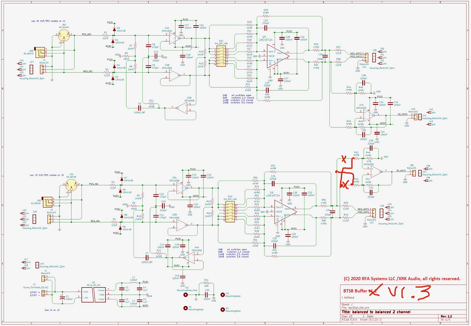
I tested out the easy fix for the v1.2 TH boards. See the red circle in the photo below for the location of the mod. It requires crossing the leads on R42 and R43. This was done on my verification board which was blue and not in ENIG finish. Some of you may have this older board (which I have offered to replace with the v1.3). However, if you have populated it already, the easy way to make it fully functional with SE output is to do the mod shown here. It’s quite easy to do. One other thing I did was made a headphone jack to connect to the SE outputs. The OPA1656 can drive up to 100mA and this is quite sufficient to drive many headphones nicely. I tested it here with my Beyer DT-880’s (250ohm) and it sounds great. So it turns out that the BTSB also doubles as a handy headphone amp!

On another prototype headphone amp I am working on, we have a pair of OPA1656’s in parallel for 4 opamps driving a headphone and I verified that it can drive 32ohm loads up to 1wrms with low distortion. Amazing little opamp.
I tested out the easy fix for the v1.2 TH boards. See the red circle in the photo below for the location of the mod. It requires crossing the leads on R42 and R43. This was done on my verification board which was blue and not in ENIG finish. Some of you may have this older board (which I have offered to replace with the v1.3). However, if you have populated it already, the easy way to make it fully functional with SE output is to do the mod shown here. It’s quite easy to do. One other thing I did was made a headphone jack to connect to the SE outputs. The OPA1656 can drive up to 100mA and this is quite sufficient to drive many headphones nicely. I tested it here with my Beyer DT-880’s (250ohm) and it sounds great. So it turns out that the BTSB also doubles as a handy headphone amp!
On another prototype headphone amp I am working on, we have a pair of OPA1656’s in parallel for 4 opamps driving a headphone and I verified that it can drive 32ohm loads up to 1wrms with low distortion. Amazing little opamp.
Attachments
BTSB TH v1.2 Fix
Does the Murata Power Supply on the board have enough current capacity to drive headphones ? I only ask because in some of the earlier messages you commented that the power supply was close to its limit and on the new boards you have adopted a higher rated Power Supply module.
Also is it necessary to solder the back of the two output Balanced Op-Amps to the pad on the PCB. Do they really create so much heat that they require a heat sink ?
Still waiting for my Mouser Order to arrive so assembly has been delayed and they are out of stock on several components !!
.
The Murata DCDC is good for about 70mA I think. Most listening levels are well below that I think. It’s probably not good for driving lower impedance phones to loud levels but for my 250ohm cans, it’s more than loud enough. Just offering it as a novelty. In a pinch it works as a headphone amp. You should add solder paste to the bottom of the LME49724 for the thermal pad to make contact with the PCB as heatsink. That is what it is designed for. If you don’t have solder paste, use liquid flux and solder from the back. But that’s iffy. It’s probably fine as long as you are not intending to drive lots of current.
For fun, I pulled out an old Wayne Kirkwood (member mediatechnology) headphone amp I made years ago based on THAT1646 driving a pair of BD139/140 in Class A push pull. It’s powered by the uber premium Yarra Mk2 active bridge TPS7A4XXX regulated power supply +/-18v and good for 1A). This headphone amp is one of the lowest distortion amps I have measured in the past. It’s only a 0dB power stage though so the BTSB was the perfect voltage gain at 14dB. It sounds quite spectacular. This amp is probably capable of up to 4W into 32ohms. It’s Class A and runs hot though. My heatsink is way too small.

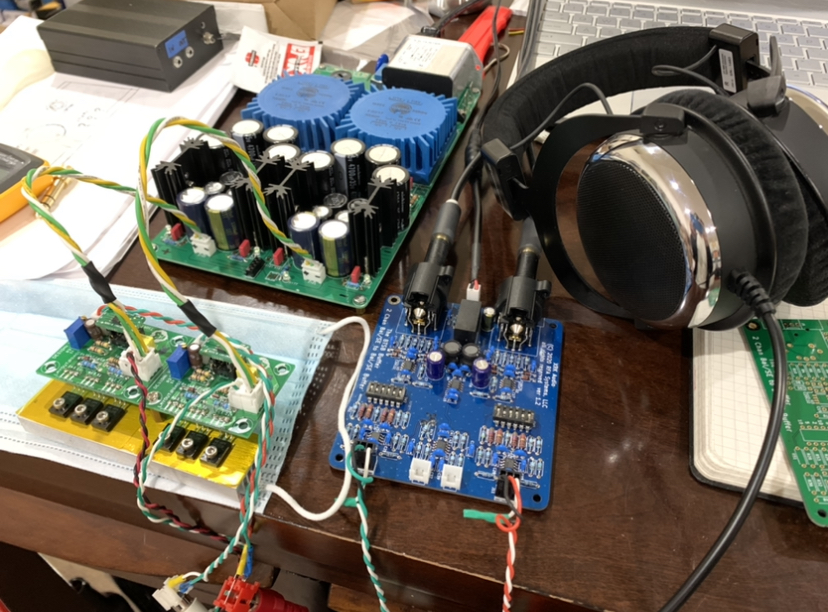
For fun, I pulled out an old Wayne Kirkwood (member mediatechnology) headphone amp I made years ago based on THAT1646 driving a pair of BD139/140 in Class A push pull. It’s powered by the uber premium Yarra Mk2 active bridge TPS7A4XXX regulated power supply +/-18v and good for 1A). This headphone amp is one of the lowest distortion amps I have measured in the past. It’s only a 0dB power stage though so the BTSB was the perfect voltage gain at 14dB. It sounds quite spectacular. This amp is probably capable of up to 4W into 32ohms. It’s Class A and runs hot though. My heatsink is way too small.
Attachments
Last edited:
Hi Folks,
Just a reminder that the BTSB Panel mount boards are now in stock if you are interested in ordering. This is a very useful board to have and can be the basis as the input front end for almost any project whether a power amp or preamp or headphone amp. If there is enough interest (say, 36 units) I could arrange for a GB to have these made ready to run. The sheet number of IC’s, relays, DCDC, and premium connectors are kind of expensive so the price will be about $200. Let me know if you would interested in something like a RTR version of this.

Just a reminder that the BTSB Panel mount boards are now in stock if you are interested in ordering. This is a very useful board to have and can be the basis as the input front end for almost any project whether a power amp or preamp or headphone amp. If there is enough interest (say, 36 units) I could arrange for a GB to have these made ready to run. The sheet number of IC’s, relays, DCDC, and premium connectors are kind of expensive so the price will be about $200. Let me know if you would interested in something like a RTR version of this.

Is there a schematic image of the BTSB TH v1.3 board? I see some slight differences from the v1.2 schematic and I want to be sure I don't make any mistakes.
It’s same as v1.2 except that the two resistors traces R42/43 are swapped.
Attachments

Last edited:
Vunce was kind enough to build up two more BTSB v1.21P panel mount boards for me. This time I wanted to test different opamps to see if others can work here. The wonderful OPA1656 orginally spec'd for the BTSB has been rather tough to find lately. There is plenty of stock on the OPA1642 (a JFET input opamp with very nice specs), and the LM4562 (a BJT input opamp, also with very nice specs regarding low distortion). So now I have an example of all three opamps and can play them side by side.
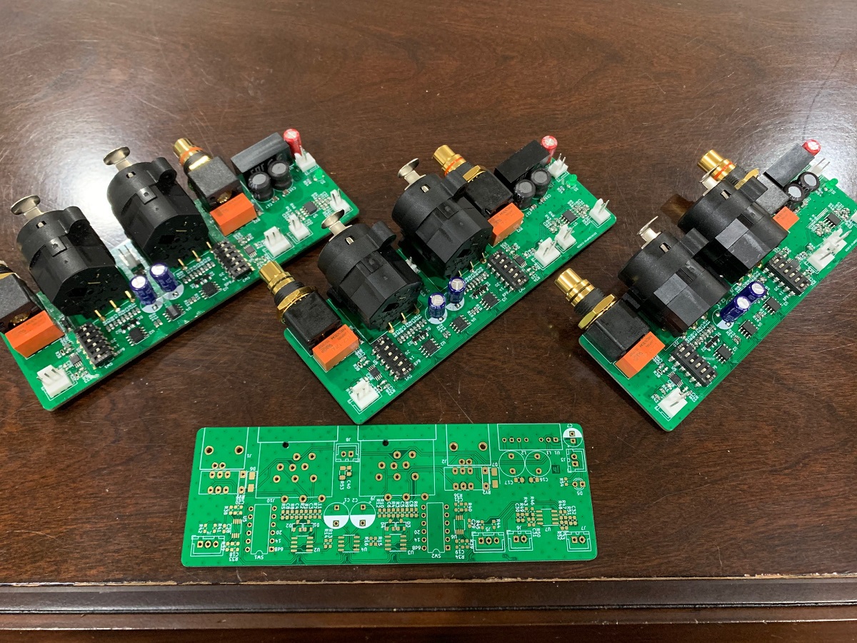
First listen was using my Focusrite 2i4 as a balanced or SE source and the BTSB woulld then drive my FH9HVX Class AB to my 10F/RS225 TL speakers. Switching between the three amps it was very hard to tell a difference. Maybe with some more extended listening I can get more info. I also tested the balanced output usiung an IcePower 1200AS2 driving my little Rockvile 5in 2-way speakers. First impression is that the OPA1642 sounds great. There are like 8000 of them in stock at Mouser and they are only $2.10ea in singles. The LM4562 sounds maybe a bit "drier" but still very clear and transparent. There are 4000 of them in stock and they are only $1.86 in singles. So it seems there are some alternatives here for the OPA1656.
Thanks for your help, Vunce!
Beautiful SMT soldering work too!
Attachments

If you ever run another order of boards consider stocking a BTSB SMT one channel version. It can be very useful in 2ch single chassis designs with tight runs from the BTSB to the main amp module (mounted on the heatsink).
The other option is to use (2) BTSB-SMT (2ch) versions but only populate 1/2 the circuit.
Best,
Anand.
The other option is to use (2) BTSB-SMT (2ch) versions but only populate 1/2 the circuit.
Best,
Anand.
I’m not sure I follow why the need for a mono BTSB? Just so that the board can be made very small? Just go with the SMT board then. You will add cost of course as separate DCDC will be needed.
I think Anand is suggesting it for dual mono, but also stereo builds, so that each buffer can be mounted right next to the poweramp board on each heatsink, so that the wiring can be shorter and more direct, rather than mounting it in the middle of the chassis and having longer wiring runs to the buffer and then to each amp.
....... so that the wiring can be shorter and more direct, rather than mounting it in the middle of the chassis and having longer wiring runs to the buffer and then to each amp.
I can see the benefit of having a mono BTSB if your building separate monoblock chassis’s.
But the panel mounted version has the most direct wiring possible. Used as is configured there is only one wiring connection to make per channel, BTSB to amp input. The wiring run is no longer than connecting amp input directly to an RCA jack on the rear panel without a BTSB.
Also, the wire from the BTSB output to the amp is low impedance and less susceptible to noise pickup. Having the panel mounted BTSB eliminates the high impedance (susceptible to noise) connection between the panel jack the BTSB.
In either case, the BTSB should be placed closer to the input wires/jacks vs close to the amp. Placing it close to the amp you will have the long run of high impedance wire through a noisy environment in the chassis.
In either case, the BTSB should be placed closer to the input wires/jacks vs close to the amp. Placing it close to the amp you will have the long run of high impedance wire through a noisy environment in the chassis.
I'm not saying its a great reason, just that that is likely his reason. I see what you mean though; the same path length is effectively travelled, wherever it is the buffer sits along that path. Unless you put the connectors placed on the outside, close to the walls rather than the center; but that would be odd. All in all a bit of a brain fart from me too; I shouldnt have attempted to be a builder whisper 😉
Last edited:
- Home
- Group Buys
- BTSB Buffer - SE/Bal to SE/Bal Buffer GB