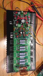
Where are your two yellow groundwires go to? I think hey're meant for supplying the input boards. If they're connected to the main GND you could have bulit a nice loop. This could cause your problems maybe...
What capacitor you have in c6? Should be in pf range, it looks like more,
Regarding soldering might just be shadows on pic, c6 if I remember correct is in feedback, and should ensure stability
Regarding soldering might just be shadows on pic, c6 if I remember correct is in feedback, and should ensure stability
Can't see insulators under the output devices in the photo. Sometimes you can get instability if the heatsink isn't grounded.
Thanks for all of your input.
So I followed the wiring in the attached document.
C6 is 68p as per schematic, its rated at 1000v which is probably why its large. It is the feedback cap.
All devices have insulators between them and the heatsink, I also checked for shorts between the heatsink and the devices. The heatsink is grounded.
Attachments
What are the voltages across R38-R41 before the voltages across the output transistor emitter resistors jumps up? Did you get your output transistors from RS or Farnell?
The voltages look ok. Did you try increasing C12 and C13 from 100pF to 150pF as suggested in the "debugging-instructions"?
I haven't, I didn't get any documentation with my boards. Would you be able to post the debug document?
Thanks for the document. I will try the caps and see what happens. I am not sure I understand why the bulb is used? Is just to protect components on initial turn in case something was installed incorrectly?
Yes if current is high, bulb lights up, resistance increases, current drops ( is limited ). 100W incandescent bulb is supposed to be good.
Brilliant, that worked! Just need to put some audio through it now, can't wait.
Many thanks for the help.
Many thanks for the help.
Transformer specs
The amplifier is working perfectly!
Just need to order the transformer and could do with some help.
I will be ordering a custom audio transformer from Toroidy.
I will be running it at around 65v so I thought that the following would work?
4 x 50v at 250Va
1 x 18v at 15Va
Just want to check before ordering.
That's 4 x 50Vac windings on a 250VA toroid? I'd say the rating is a bit on the low side, 500VA would be a bit more like it. You probably don't want more than 70-75Vdc after rectification and smoothing so bear in mind that although the UK ac mains is nominally 230V its actually 240V. I'd either get the primary wound for 240V or get 45Vac secondaries
- Home
- Amplifiers
- Solid State
- Bryston 4B SST clone