This is the best seller on ebay, his name is Liu, store name Pinshuche.
He’s very supportive and very nice.
Here’s the link for amp boards but he slso has psu and input boards kit, too:
Pinshuche on ebay
He’s very supportive and very nice.
Here’s the link for amp boards but he slso has psu and input boards kit, too:
Pinshuche on ebay
Hi I'm interested in this product, before purchase from ebay or aliexpress, a question want to ask to those already did, are there any obsolete /hard-to-find parts needed? If buy the kits with components, the authenticity is always a question with Chinese sellers, haven't you seen any issue?
PS, anyone bought assembled boards? I'm getting old and lazy.
PS, anyone bought assembled boards? I'm getting old and lazy.

Hi, what is main, optimal secondary transformer AC voltage? Chinese wrote that AC 32 to 60V. But need optimal for sound quality.
I copy and paste the suggestion I got from bengtx600 here above about tranny:
"You can use two Antek AN-5450, AN-6450, or one AN-10450. You can also or to can easily use two AN-5455, AN-6455, or one AN-10455, AN-10458 (Two 500VA is Ok, or one 1000VA is Ok also) Up to 58Vac max. More you put voltage more tight must be the transistor matching.”
Please guys read the entire thread, I know it is very long but it worths to know more for the building.
Hope this helps! ;-)
There are really no hard to find parts. Using the kit would be my suggestion. That way you have all the parts and can make changes or substitutions as necessary. Matching transistor pairs as closely as possible is key to a good amp. The PN100,200’s in my kit were not good enough so I purchased 50 of each and was able to get good matches. Apparently these are only available from China and I got mine on EBay. The output transistors are readily available from Mouser, DigiKey, etc. I did replace some caps that didn’t match the BOM. The power supply is quite substantial and you would want to use good caps there. Hope this helps.
I’m about ready to give up on this project. Can’t get past the initial start setup. Both boards have -5.5 vdc on the output. I have 33 vdc, but neither vr1 or vr2 have any effect. I seem to remember another builder having this issue and never getting it resolved. Anyone have any ideas?
hi furnman..
1. Check Power Supply Rails: Confirm ±33 V relative to ground on both amplifier boards. Make sure ground is properly connected to the center tap of the transformer.
2. Verify Potentiometers (VR1/VR2): Measure across the potentiometers to ensure they change resistance. Check if voltage on the wiper (middle pin) responds to adjustment.
3. Inspect Transistors: Double-check orientation and type (NPN/PNP) of input and VAS transistors. Reversed or incorrect parts can cause DC offset.
4. Measure Key Voltages: Measure base, collector, and emitter voltages on the input differential pair, VAS, and bias transistors. Compare with the schematic.
5. Compare Channels: If both boards behave identically, the issue may be with shared power supply or grounding.
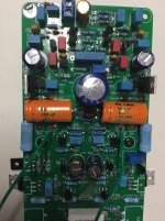
Post clear photos of both sides of your PCB, especially around Q1–Q4, VR1/VR2, R11–R14 area.
1. Check Power Supply Rails: Confirm ±33 V relative to ground on both amplifier boards. Make sure ground is properly connected to the center tap of the transformer.
2. Verify Potentiometers (VR1/VR2): Measure across the potentiometers to ensure they change resistance. Check if voltage on the wiper (middle pin) responds to adjustment.
3. Inspect Transistors: Double-check orientation and type (NPN/PNP) of input and VAS transistors. Reversed or incorrect parts can cause DC offset.
4. Measure Key Voltages: Measure base, collector, and emitter voltages on the input differential pair, VAS, and bias transistors. Compare with the schematic.
5. Compare Channels: If both boards behave identically, the issue may be with shared power supply or grounding.
Post clear photos of both sides of your PCB, especially around Q1–Q4, VR1/VR2, R11–R14 area.
Last edited:
Widzę pewne różnice pomiędzy wejściem rev:3 i rev:4. Wartości rezystancji dla R43 i 44 są różne. W rev 4.0 wynosi ona 3,9k, a w rev 3.0 220 omów.
Hello amp,
Thanks for the response. The power supply is good and doesn’t seem to be the problem. My suspicion at this point is the transistors. I bought 50 of each and tested them all, but who knows whether they are counterfeit or not. I might order another set of boards and use 5401-5551’s, or just keep the power supply and use it in another project. Thanks again for the suggestions.
Thanks for the response. The power supply is good and doesn’t seem to be the problem. My suspicion at this point is the transistors. I bought 50 of each and tested them all, but who knows whether they are counterfeit or not. I might order another set of boards and use 5401-5551’s, or just keep the power supply and use it in another project. Thanks again for the suggestions.
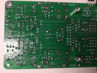
Hi.. yes photos suffer from glare, vert hard to se area q1-q4.. could be helpful with better photos..Please confirm the pinout orientation of Q1–Q4. You're using BC550/560, which have a C-B-E layout, not E-B-C like the silkscreen might suggest. If inserted according to the PCB print, they may be reversed — and this would explain your -25 V on all bases.
2. Double-check R11 and surrounding resistors (R12–R14) for damage or bad solder joints. You mentioned R11 smelled burnt — that may affect feedback/biasing.
3. Measure voltages again after letting the board settle for 2–3 minutes with the bulb limiter connected. Focus on:
Vb Q1 and Q2
Voltage across VR1 and VR2 wipers
Voltage across R41 and R45
Amp,
You might have me confused with hschier. Looked back in the thread and he had the same issue. He used bc550-560 where I used pn100. He never posted whether he got the amp working. Regards.
You might have me confused with hschier. Looked back in the thread and he had the same issue. He used bc550-560 where I used pn100. He never posted whether he got the amp working. Regards.
- Home
- Amplifiers
- Solid State
- Bryston 4B SST clone