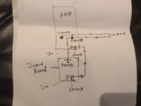
When SGND is disconnected, measure if there is voltage between SGND and GND
Thanks nico....after disconnecting output cable from input board to AMP(SGND+input)
1)no voltage between AMP SGND AND GND
2)+30V Between input board SGND AND GND....+30V Between INPUT BOARD sig in and GND ?
THANKS
The input board has a PGND and an SGND, have you connected them together somewhere? You must do this if you're testing the input board by itself. I got caught like this. Otherwise follow the wiring diagram that comes with the documentation.
The input board has a PGND and an SGND, have you connected them together somewhere? You must do this if you're testing the input board by itself. I got caught like this. Otherwise follow the wiring diagram that comes with the documentation.
Thanks chalky...please check my final wiring diagram.
Attachments
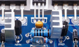
I calculate that Q5-6 are dissipating 370mW in normal operation so I guess that they would get pretty hot. 370mW is quite a lot for a TO92 package. If Q1-4 are cold, Q5-6 hot, and Q7-8 warm with SGND connected then I think this is ok ( assuming that you're using 150R and 2N5401/5551 for Q6/5 ). The 2N5401/5551 can dissipate 625mW ( as can the original PN100/200 ) but its not a good idea to run parts hot. The BC546C/556C can only dissipate 500mW so it would run even hotter. Must admit that I didn't notice how hot Q5/6 got on my input board. In the interests of device longevity I'd epoxy small heatsinks onto Q5/6. I'll poke around to see if I can find any better options for Q5/6.
I calculate that Q5-6 are dissipating 370mW in normal operation so I guess that they would get pretty hot. 370mW is quite a lot for a TO92 package. If Q1-4 are cold, Q5-6 hot, and Q7-8 warm with SGND connected then I think this is ok ( assuming that you're using 150R and 2N5401/5551 for Q6/5 ). The 2N5401/5551 can dissipate 625mW ( as can the original PN100/200 ) but its not a good idea to run parts hot. The BC546C/556C can only dissipate 500mW so it would run even hotter. Must admit that I didn't notice how hot Q5/6 got on my input board. In the interests of device longevity I'd epoxy small heatsinks onto Q5/6. I'll poke around to see if I can find any better options for Q5/6.
Thanks Chalky....you have done lot of things for me as well as for Thais thread users.i will precede with heatsink.if you can please give better solution for Q5/6 I will wait for you.
Another thing chalky..I tried to learn mechanism of action and physics of each steps and special components of power amplifier. I googled lot of lecture notes, short notes but did not find any good simple material .I kindly request you to as a expert please make a short note in relation to “THIS AMP” and give us.It may highly useful for this thread users.PDF is better.
Thanks
The only drop in replacements I've come up with so far are the ZTX653 ( npn ) for Q5 and ZTX753 ( pnp ) for Q6 which can dissipate 1W. I don't really understand why the vas current has to be so high and equal to the bias current of the class A output stage ( Q7/8 ). I've ordered a couple of the simple input boards like yours to experiment with and when they come I'll post my findings here. As regards analysis of simple, discrete op amp circuits I think that Douglas Self's or Bob Cordell's books do a far better job that I would be able to. In any event the analysis would take several pages and is not really appropriate for a forum discussion.
The only drop in replacements I've come up with so far are the ZTX653 ( npn ) for Q5 and ZTX753 ( pnp ) for Q6 which can dissipate 1W. I don't really understand why the vas current has to be so high and equal to the bias current of the class A output stage ( Q7/8 ). I've ordered a couple of the simple input boards like yours to experiment with and when they come I'll post my findings here. As regards analysis of simple, discrete op amp circuits I think that Douglas Self's or Bob Cordell's books do a far better job that I would be able to. In any event the analysis would take several pages and is not really appropriate for a forum discussion.
Thank you very much Chalky for your valuable contribution.will wait for your updates...
Actually I think the 2N5401/2N5551 for Q6,Q5 is probably the best bet. They are cheap, readily available ( at the moment ), and although the free air dissipation is 625mW the collector dissipation is 1.5W. So heatsinks would definitely be a help for now. But as I said I don't really see why the vas current has to be so high; so when my new boards come I'll recalculate a few component values to see if I can get the vas current down without compromising the overall performance.
Actually I think the 2N5401/2N5551 for Q6,Q5 is probably the best bet. They are cheap, readily available ( at the moment ), and although the free air dissipation is 625mW the collector dissipation is 1.5W. So heatsinks would definitely be a help for now. But as I said I don't really see why the vas current has to be so high; so when my new boards come I'll recalculate a few component values to see if I can get the vas current down without compromising the overall performance.
Thanks Chalky....will wait for you......
Hi Guys
Epoxying heatsinks on doesn't sound like a good idea since the epoxy adds thermal resistance. In the past, there were clip-ons for TO-98s and similar.
The older Bryston models used 2N5551 and 2N4501 in a few places, such as for the protection circuit, for the predrivers and drivers. They still used these up to the SST2 era. Now they are using SM parts in the front-end and anywhere the signal swing does not exceed 120V.
Note that Bryston's designs do exhibit some hotter running parts than one might expect and these have to survive the 100-hour burn-in. They know what they are doing.
I found the circuits not to sim well, but I suspect part of that has to do with the models available to us common folk? Bryston has some very talented people who no doubt have made more accurate models for the parts they use. They also have the best test equipment available to be able to match devices and verify circuit performance, even if that verification is that the AP cannot find any THD 🙂
Bryston often does things in simpler ways than you expect. Performance does not require sophistication or complexity; sometimes just elegance.
If it runs hot it dies young. Physics fact. A thin layer of silver loaded epoxy has a very low thermal resistance - used for high power leds all the time. You can still get to92 clip on heatsinks but they're not very good because they are physically small and the contact area with the semiconductor is also small. The design that is being copied here is 30 years old and things have moved on a bit since then. Bryston themselves have improved on the 4B SST. Some of the parts that Bryston used are are unobtainium and so the most suitable modern equivalents must be found - and if necessary the circuit modified to accommodate them.
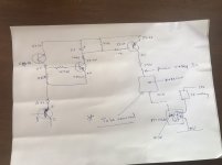
Hi chalky and other experts please do a favour for me.I have Yamaha V890 which having malfunctioning processor .i reconstruct amplifier part and enjoying with it.i want to switch on speaker protection relay preserving it protecting function so please redesign it in simple way without processor. Schematic is attached.(sorry this not related to topic)
Thanks
Thanks
Attachments
Last edited:
I try to build the version 3B sst on chinese pcb ``across audio``. some parts are hard to find or are backorder.
Have you tried good replacement for PN100A, PN200A, E202 (2mA diode) ?
For this 3B version in the BOM are MJE15034-15035 or MJE15030-15031 (last one is backorder). Which option is better?
Have you tried good replacement for PN100A, PN200A, E202 (2mA diode) ?
For this 3B version in the BOM are MJE15034-15035 or MJE15030-15031 (last one is backorder). Which option is better?
I try to build the version 3B sst on chinese pcb ``across audio``. some parts are hard to find or are backorder.
Have you tried good replacement for PN100A, PN200A, E202 (2mA diode) ?
For this 3B version in the BOM are MJE15034-15035 or MJE15030-15031 (last one is backorder). Which option is better?
Hi...warmly welcome ...my advise is you need good practical experience for this board so please read in and out from page 1 again and again all the answers are there.
The BC550C/60C are pretty good for use in those input stages. I've done a lot of simulations with those. They have very high gain and they're just about the lowest noise parts you can find.
- Home
- Amplifiers
- Solid State
- Bryston 4B SST clone